HP dx2310 Service Reference Guide: HP Compaq dx2310 MT/dx2318 MT Business PCs, - Page 60
System Board, Heatsink - MT chassis
 |
View all HP dx2310 manuals
Add to My Manuals
Save this manual to your list of manuals |
Page 60 highlights
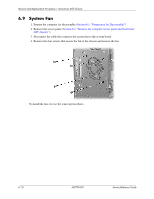
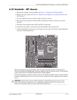
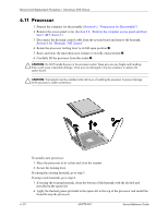
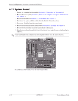
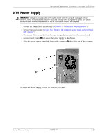
Removal and Replacement Procedures- Microtower (MT) Chassis 6.12 System Board 1. Prepare the computer for disassembly (Section 6.1, "Preparation for Disassembly"). 2. Remove the access panel (Section 6.2, "Remove the computer access panel and front bezel (MT chassis)"). 3. Remove the front bezel (Section 6.2.2, "Front Bezel (MT Chassis)"). 4. Disconnect the power, and data cables from the back of all installed drives. 5. Disconnect all cables from the system board. 6. Remove the heatsink from the system board (Section 6.10, "Heatsink - MT chassis"). 7. Remove the 6 screws that secure the system board to the chassis. 8. Slide the system board towards the front of the chassis then, angle the back of the board up to remove it. ✎ The system board in the computer may look slightly different from the one shown here. To install the system board, reverse the removal procedure.. 6-22 490778-001 Service Reference Guide
-
 1
1 -
2
-
3
-
4
-
5
-
6
-
7
-
8
-
9
-
10
-
11
-
12
-
13
-
14
-
15
-
16
-
17
-
18
-
19
-
20
-
21
-
22
-
23
-
24
-
25
-
26
-
27
-
28
-
29
-
30
-
31
-
32
-
33
-
34
-
35
-
36
-
37
-
38
-
39
-
40
-
41
-
42
-
43
-
44
-
45
-
46
-
47
-
48
-
49
-
50
-
51
-
52
-
53
-
54
-
 55
55 -
 56
56 -
 57
57 -
 58
58 -
 59
59 -
 60
60 -
 61
61 -
 62
62 -
 63
63 -
 64
64 -
 65
65 -
66
-
67
-
68
-
69
-
70
-
71
-
72
-
73
-
74
-
75
-
76
-
77
-
78
-
79
-
80
-
81
-
82
-
83
-
84
-
85
-
86
-
87
-
88
-
89
-
90
-
91
-
92
-
93
-
94
-
95
-
96
-
97
 |
 |
