IBM 17011RS Maintenance Manual
IBM 17011RS - TotalStorage DS300 Model NAS Server Manual
 |
UPC - 000435304971
View all IBM 17011RS manuals
Add to My Manuals
Save this manual to your list of manuals |
IBM 17011RS manual content summary:
- IBM 17011RS | Maintenance Manual - Page 1
IBM TotalStorage DS300 and DS400 Hardware Maintenance Manual - IBM 17011RS | Maintenance Manual - Page 2
- IBM 17011RS | Maintenance Manual - Page 3
IBM TotalStorage DS300 and DS400 Hardware Maintenance Manual - IBM 17011RS | Maintenance Manual - Page 4
Note Before using this information and the product it supports, be sure to read the general information in Appendix C, "Notices," on page 57. Fifth Edition (October 2005) © . US Government Users Restricted Rights - Use, duplication or disclosure restricted by GSA ADP Schedule Contract with IBM Corp. - IBM 17011RS | Maintenance Manual - Page 5
, leggere le Informazioni sulla Sicurezza. Les sikkerhetsinformasjonen (Safety Information) før du installerer dette produktet. Antes de instalar este produto, leia as Informações sobre Segurança. © Copyright IBM Corp. 2004, 2005 iii - IBM 17011RS | Maintenance Manual - Page 6
Antes de instalar este producto, lea la información de seguridad. Läs säkerhetsinformationen innan du installerar den här produkten. iv IBM TotalStorage DS300 and DS400: Hardware Maintenance Manual - IBM 17011RS | Maintenance Manual - Page 7
with a number 1, translations for that caution statement appear in the IBM Safety Information book under statement 1. Be sure to read all caution and danger statements in this documentation before performing the instructions. Read any additional safety information that comes with your server or - IBM 17011RS | Maintenance Manual - Page 8
Statement 2: CAUTION: When replacing the lithium battery, use only IBM Part Number 33F8354 or an equivalent type battery recommended by the manufacturer. disassemble Dispose of the battery as required by local ordinances or regulations. vi IBM TotalStorage DS300 and DS400: Hardware Maintenance Manual - IBM 17011RS | Maintenance Manual - Page 9
: v Do not remove the covers. Removing the covers of the laser product could result in exposure to hazardous laser radiation. There are no serviceable parts inside the device. v Use of controls or adjustments or performance of procedures other than those specified herein might result in hazardous - IBM 17011RS | Maintenance Manual - Page 10
more than one power cord. To remove all electrical current from the device, ensure that all power cords are disconnected from the power source. 2 1 viii IBM TotalStorage DS300 and DS400: Hardware Maintenance Manual - IBM 17011RS | Maintenance Manual - Page 11
, and energy levels are present inside any component that has this label attached. There are no serviceable parts inside these components. If you suspect a problem with one of these parts, contact a service technician. Statement 10: CAUTION: Do not place any object weighing more than 82 kg (180 lb - IBM 17011RS | Maintenance Manual - Page 12
x IBM TotalStorage DS300 and DS400: Hardware Maintenance Manual - IBM 17011RS | Maintenance Manual - Page 13
IBM TotalStorage DS300 storage subsystem type 1701 (models 1RL, 1RS, 2RD 5 General checkout 5 General information 5 Additional service and information from the World Wide Web 56 Software service and support 56 Hardware service and support 56 Appendix C. Notices 57 Edition notice 57 Trademarks - IBM 17011RS | Maintenance Manual - Page 14
xii IBM TotalStorage DS300 and DS400: Hardware Maintenance Manual - IBM 17011RS | Maintenance Manual - Page 15
determination procedures provided in the IBM TotalStorage DS300 Problem Determination Guide and DS400 Problem Determination Guide. Each Problem Determination Guide is an interactive document that is available on the IBM support Web site: http://www.ibm.com/pc/support/site.wss/document.do?lndocid - IBM 17011RS | Maintenance Manual - Page 16
Chapter 2, "IBM TotalStorage DS300 storage subsystem type 1701 (models 1RL, 1RS, 2RD)," on page 5 provides service and diagnostic problem situations. v Attention: These notices indicate possible damage to programs, devices, or data. An attention notice is placed just before the instruction - IBM 17011RS | Maintenance Manual - Page 17
documentation for your storage subsystem in Portable Document Format (PDF) and includes the IBM Documentation Browser to help you find information quickly. Hardware and software requirements The IBM Documentation CD requires the following minimum hardware and software: v Microsoft® Windows® 2000, or - IBM 17011RS | Maintenance Manual - Page 18
printed document contains instructions for installing the storage subsystem in a rack. v IBM TotalStorage DS300 Problem Determination Guide and IBM TotalStorage DS400 Problem Determination Guide Each Problem Determination Guide is an interactive document that is available on the IBM Support Web site - IBM 17011RS | Maintenance Manual - Page 19
during and after installation. It uses flowcharting techniques to guide you in the isolation and correction of problems. General information There are three models of the DS300 storage subsystem type 1701 (models 1RL, 1RS, 2RD). v The IBM TotalStorage DS300 storage subsystem model 1RL comes with the - IBM 17011RS | Maintenance Manual - Page 20
section provides additional service information about The declared sound-power levels indicate an upper limit, below which a large number of computers will operate Electrical input v Sine-wave input (50 to 60 Hz) is required replaced. 6 IBM TotalStorage DS300 and DS400: Hardware Maintenance Manual - IBM 17011RS | Maintenance Manual - Page 21
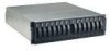
hardware. Hard disk drive Drive filler panel Figure 1. DS300 (type 1701 (models 1RS, 2RD) storage subsystem front components Hard disk drive You can install (model 1RL) storage subsystem front components Chapter 2. IBM TotalStorage DS300 storage subsystem type 1701 (models 1RL, 1RS, 2RD) 7 - IBM 17011RS | Maintenance Manual - Page 22
The DS300 (model 1RL) storage subsystem supports seven hard disk drives. You can add seven more hard disk (Side A) RAID controller filler panel (Side B) Figure 3. DS300 storage subsystem model 1RS rear view Power supply Power supply filler panel ISCSI RAID controller with one Gb Ethernet - IBM 17011RS | Maintenance Manual - Page 23
controller in model 1RL does not contain a cache battery. The DS300 storage subsystem model 1RS contains one iSCSI RAID controller with one 1 Gb/sec Ethernet input connector for management, be installed in side A. Chapter 2. IBM TotalStorage DS300 storage subsystem type 1701 (models 1RL, 1RS, 2RD) 9 - IBM 17011RS | Maintenance Manual - Page 24
the power supply is turned on. Fault LED (amber) When this LED is lit, there is a fault with either the power supply or a fan. 10 IBM TotalStorage DS300 and DS400: Hardware Maintenance Manual - IBM 17011RS | Maintenance Manual - Page 25
iSCSI data traffic. iSCSI RAID controller with three Ethernet connectors type 1701 (models 1RS, 2RD): The iSCSI RAID controller with three Ethernet connectors has 12 ETH 3 connector is for iSCSI data transfer. Chapter 2. IBM TotalStorage DS300 storage subsystem type 1701 (models 1RL, 1RS, 2RD) 11 - IBM 17011RS | Maintenance Manual - Page 26
The service life 1701 (models 1RL, 1RS, 2RD), use the following diagnostic tools: v ServeRAID Manager software v LEDs and the "Symptom-to-FRU index" on page 13 For additional help when diagnosing problems with the DS400 storage subsystem, refer to the DS300 and DS400 Problem Determination Guides IBM - IBM 17011RS | Maintenance Manual - Page 27
from the ServeRAID Manager (Save Support Archive) to capture the state of the controllers at the time of the failure. You can now correct the fault before you turn off the power. See the problem determination maps in the DS300 and DS400 Problem Determination Guide for more detailed procedures for - IBM 17011RS | Maintenance Manual - Page 28
instructions 1701 Guide. Table 3. Symptom-to-FRU index for power supply LEDs Symbol Problem Indicator Green Power Supply Power LED is off. Action Verify that the power cord is plugged in and that the storage subsystem power is on. 14 IBM TotalStorage DS300 and DS400: Hardware Maintenance Manual - IBM 17011RS | Maintenance Manual - Page 29
Symbol Problem Indicator Action Amber Fault LED is lit solidly. Replace the power supply (p/n 13N1784). The amber Fault LED will be ON solid when the enclosure services module current is out of range. Chapter 2. IBM TotalStorage DS300 storage subsystem type 1701 (models 1RL, 1RS, 2RD) 15 - IBM 17011RS | Maintenance Manual - Page 30
LED will go on and the DS300 type 1701 (model 1RL because it does not support a cache. IBM support When this LED is lit, it indicates that the representative to attempt to recover the controller. controller is not ready. IBM personnel only: Refer to the DS300 and DS400 Problem Determination Guide - IBM 17011RS | Maintenance Manual - Page 31
: If you cannot find the problem in the Symptom-to-FRU index, refer to the DS300 and DS400 Problem Determination Guide. The following figures and table provide a parts listing for the DS300 storage subsystem type 1701 (models 1RL, 1RS, 2RD). Chapter 2. IBM TotalStorage DS300 storage subsystem type - IBM 17011RS | Maintenance Manual - Page 32
1701 (models 1RL, 1RS, 2RD) storage subsystem parts list Index 1 2 3 4 and 5 6 7 8 9 10 10 11 12 13 14 15 DS300 storage subsystem (models 1RL, 1RS, cache (models 1RS, 2RD) Battery, (real-time clock, CR1220) (all models) Power supply (all models) Cable, serial (For use by IBM service personnel only - IBM 17011RS | Maintenance Manual - Page 33
Index DS300 storage subsystem (models 1RL, 1RS, 2RD) Miscellaneous hardware kit, including: (all models) v Ethernet wrap plug (00G2380) v 2 M6 hex screws discussed in this document by country and region. Chapter 2. IBM TotalStorage DS300 storage subsystem type 1701 (models 1RL, 1RS, 2RD) 19 - IBM 17011RS | Maintenance Manual - Page 34
20 IBM TotalStorage DS300 and DS400: Hardware Maintenance Manual - IBM 17011RS | Maintenance Manual - Page 35
storage subsystem during and after installation. It uses flowcharting techniques to guide you in the isolation and correction of problems. General information The IBM TotalStorage DS400 storage subsystem model 1700-1RS comes with the following components: v One Fibre Channel RAID controller v 14 - IBM 17011RS | Maintenance Manual - Page 36
sound-power levels indicate an upper limit, below which a large number of computers will operate Storage subsystem components The following sections show the components of the storage might differ slightly from your hardware. 22 IBM TotalStorage DS300 and DS400: Hardware Maintenance Manual - IBM 17011RS | Maintenance Manual - Page 37
rear of the DS400 storage subsystem. Power supplies Fibre Channel RAID controller (Side A) RAID controller filler panel (Side B) Figure 12. DS400 storage subsystem model 1700-1RS rear view Chapter 3. IBM TotalStorage DS400 type 1700 (models 1RS, 2RD) storage subsystem 23 - IBM 17011RS | Maintenance Manual - Page 38
LED Locator LED Storage subsystem fault LED Hard disk drive activity LED Hard disk drive status LED Figure 14. DS400 storage subsystem front LEDs 24 IBM TotalStorage DS300 and DS400: Hardware Maintenance Manual - IBM 17011RS | Maintenance Manual - Page 39
connectors, depending on the storage subsystem model. The following illustration shows the LEDs and connectors on the DS400 storage subsystem Fibre Channel RAID controller. Chapter 3. IBM TotalStorage DS400 type 1700 (models 1RS, 2RD) storage subsystem 25 - IBM 17011RS | Maintenance Manual - Page 40
service problems on the DS400 storage subsystem, use the following diagnostic tools: v ServeRAID Manager software v LEDs and the "Symptom-to-FRU index" on page 27 v Sansurfer Pro (see the DS300 and DS400 Problem Determination Guide) 26 IBM TotalStorage DS300 and DS400: Hardware Maintenance Manual - IBM 17011RS | Maintenance Manual - Page 41
. You can also order the fibre channel wrap plug kit (IBM Part Number 24P0950). This wrap plug kit is used to identify DS400 fibre channel path problems. See the DS300 and DS400 Problem Determination Guide for more information. Symptom-to-FRU index Use the ServeRAID Manager software to diagnose - IBM 17011RS | Maintenance Manual - Page 42
(Save Support Archive) problem. For more information, see the DS300 and DS400 Problem Determination Guide. 1. Check the LEDs for all components on enclosure (disk drives, power supplies, controllers) and follow the solution instructions IBM TotalStorage DS300 and DS400: Hardware Maintenance Manual - IBM 17011RS | Maintenance Manual - Page 43
troubleshooting drive-side issues, refer to the Drive Side PD Map in the DS300 and DS400 Problem Determination Guide. Table 7. Symptom-to-FRU index for power supply LEDs Symbol Problem current is out of range. Chapter 3. IBM TotalStorage DS400 type 1700 (models 1RS, 2RD) storage subsystem 29 - IBM 17011RS | Maintenance Manual - Page 44
controller cache. The Cache Dirty LED will go on and off at varying rates and durations IBM support When this LED is lit, it indicates that the representative to attempt to recover the controller. controller is not ready. IBM personnel only: Refer to the DS300 and DS400 Problem Determination Guide - IBM 17011RS | Maintenance Manual - Page 45
you cannot find the problem in the Symptom-to-FRU index, refer to the DS300 and DS400 Problem Determination Guides. Figure 17 on page 32 and the following table provide a parts listing for the DS400 storage subsystem type 1701 (models 1RS, 2RD). Chapter 3. IBM TotalStorage DS400 type 1700 (models - IBM 17011RS | Maintenance Manual - Page 46
(model 1RS) FC controller (all models) (shipped without battery and memory cache) Memory, Cache-DIMM: 256 MB (all models) Memory, System -DIMM: 1 GB (all models) Battery (real-time clock, CR1220 (all models) Battery, cache (all models) Power supply (all models) Cable, serial (For use by IBM service - IBM 17011RS | Maintenance Manual - Page 47
24P0950 CRU CRU "Power cords" on page 61 lists required power cords for the storage components discussed in this document by country and region. Chapter 3. IBM TotalStorage DS400 type 1700 (models 1RS, 2RD) storage subsystem 33 - IBM 17011RS | Maintenance Manual - Page 48
34 IBM TotalStorage DS300 and DS400: Hardware Maintenance Manual - IBM 17011RS | Maintenance Manual - Page 49
can also indicate touch points on hot-swap components.) See the instructions for removing or installing a specific hot-swap component for any additional the component. v For a list of supported options for the storage subsystem, go to http://www.ibm.com/pc/compat/. System reliability guidelines To - IBM 17011RS | Maintenance Manual - Page 50
Installing and removing the bezel on DS300 Models 1700-1RS and 1700-2RD, and DS400 Note: Before installing the rack. For more information, see the Rack Mounting Instructions that come with the storage subsystem. Complete the following IBM TotalStorage DS300 and DS400: Hardware Maintenance Manual - IBM 17011RS | Maintenance Manual - Page 51
safe place. Installing and removing the bezel on the DS300 type 1701 (model 1RL) Note: Before installing the bezel on the storage subsystem, install it in the rack. For more information, see the Rack Mounting Instructions that come with the storage subsystem. Complete the following steps to install - IBM 17011RS | Maintenance Manual - Page 52
hard disk drive The storage subsystem supports up to 14 IBM Ultra320 SCSI hard disk drives. These IBM drives come preassembled in a hot-swap hard disk drive" on page 39 for more information. 1. Read the instructions that come with the hard disk drive. 2. Read the safety information beginning on page - IBM 17011RS | Maintenance Manual - Page 53
. Replacing a hot-swap hard disk drive Hard disk drive problems include any malfunctions that delay, interrupt, or prevent successful I/O following steps to replace a hot-swap hard disk drive: 1. Read the instructions that come with the hard disk drive. 2. Read the safety information beginning - IBM 17011RS | Maintenance Manual - Page 54
or immerse into water v Heat to more than 100°C (212°F) v Repair or disassemble Dispose of the battery as required by local ordinances or regulations. 40 IBM TotalStorage DS300 and DS400: Hardware Maintenance Manual - IBM 17011RS | Maintenance Manual - Page 55
loss, you must shut down the system before you replace the battery. For the correct shutdown sequence, refer to the Hardware Installation and User's Guide. 1. Read the safety information beginning on page iii and "Installation guidelines" on page 35. 2. Label each cable that is connected to the RAID - IBM 17011RS | Maintenance Manual - Page 56
: a. Make sure that the lever on each side of the controller is down as far as it will go. b. Push the controller into the bay until it meets resistance (approximately 6 mm [0.25 in.] from the the format: system date hh:mm:ss@dd/mm/yy 42 IBM TotalStorage DS300 and DS400: Hardware Maintenance Manual - IBM 17011RS | Maintenance Manual - Page 57
: The iSCSI RAID controller in the DS300 model 1701-1RL does not contain a cache battery. Each to the unit. If the ServeRAID Manager program instructs you to replace the battery because the current battery to the ″Hardware Installation and User's Guide″. Attention: When you handle static-sensitive - IBM 17011RS | Maintenance Manual - Page 58
battery. 12. Install the new cache battery into the RAID controller: a. Slide the battery under the tab near the front of the RAID controller. 44 IBM TotalStorage DS300 and DS400: Hardware Maintenance Manual - IBM 17011RS | Maintenance Manual - Page 59
the thumbscrew. 13. Install the RAID controller: a. Make sure that the lever on each side of the controller is down as far as it will go. b. Push the controller into the bay until it meets resistance (approximately 6 mm [0.25 in.] from the end of the chassis). c. While squeezing together the latch - IBM 17011RS | Maintenance Manual - Page 60
from the RAID controller. For more information refer to the Hardware Installation and User's Guide. Attention: When you handle static-sensitive devices, take precautions to avoid damage from will slide out of the bay a short distance. 46 IBM TotalStorage DS300 and DS400: Hardware Maintenance Manual - IBM 17011RS | Maintenance Manual - Page 61
RAID controller RAID controller filler panel Figure 26. Removing a RAID controller b. Grasp both latches and pull the controller out of the bay. c. Place the controller on a dry, level surface. Attention: To avoid breaking the retaining clips or damaging the DIMM connectors, open and close the - IBM 17011RS | Maintenance Manual - Page 62
each side of the controller is down as far as it will go. b. Push the controller into the bay until it meets resistance to the original controller. Replacing a RAID controller When instructed to do so by the ServeRAID Manager program, IBM TotalStorage DS300 and DS400: Hardware Maintenance Manual - IBM 17011RS | Maintenance Manual - Page 63
in the following procedure. 2. The RAID controller in the DS300 model 1701-1RL does not contain a cache battery. Replacing the hardware To replace optic cables and SFP modules, refer to the ″Hardware Installation and User's Guide″. 5. Remove the failed controller (the fault LED is lit): a. While - IBM 17011RS | Maintenance Manual - Page 64
reinsert it. Note: The replacement RAID controller comes with a 512 MB system DIMM installed. If you upgraded the system DIMM to 1 GB, follow steps 9 50 IBM TotalStorage DS300 and DS400: Hardware Maintenance Manual - IBM 17011RS | Maintenance Manual - Page 65
lever on each side of the controller is down as far as it will go. b. Push the controller into the bay until it meets resistance (approximately 6 together the latch and lever, push both latches up as far as they will go. The controller slides the rest of the way into the bay. 12. Reconnect - IBM 17011RS | Maintenance Manual - Page 66
save the modified settings. See the IBM TotalStorage DS300 Problem Determination Guide or IBM TotalStorage DS400 Problem Determination Guide on the IBM Support Web site for a list of all Foreign array and select Import foreign array. 52 IBM TotalStorage DS300 and DS400: Hardware Maintenance Manual - IBM 17011RS | Maintenance Manual - Page 67
proper expansion unit cooling. v Use only power supplies that are supported for your specific storage subsystem. Complete the following steps to replace the lever on each side of the power supply is down as far as it will go. b. Push the power supply into the bay until it meets resistance (about 6 - IBM 17011RS | Maintenance Manual - Page 68
c. While squeezing together the latch and lever, push both latches up as far as they will go. The power supply will slide the rest of the way into the bay. 7. Connect the fault (amber) LED is off and the Power OK (green) LEDs are lit. 54 IBM TotalStorage DS300 and DS400: Hardware Maintenance Manual - IBM 17011RS | Maintenance Manual - Page 69
the troubleshooting information in your system documentation, and use the diagnostic tools that come with your system. Information about diagnostic tools is in the DS300 and DS400 Problem Determination Guides and the Hardware Maintenance Manual at the IBM Support Web site. v Go to the IBM Support - IBM 17011RS | Maintenance Manual - Page 70
and software problems with xSeries servers, IntelliStation workstations, and appliances. For information about which products are supported by Support Line in your country or region, go to http://www.ibm.com/services/sl/products/. For more information about Support Line and other IBM services, go to - IBM 17011RS | Maintenance Manual - Page 71
right may be used instead. However, it is the user's responsibility to evaluate and verify the operation of any non-IBM product, program, or service. IBM may have patents or pending patent applications covering subject matter described in this document. The furnishing of this document does not - IBM 17011RS | Maintenance Manual - Page 72
disk drive bays with the largest currently supported drives available from IBM. Maximum memory may require replacement of the standard memory with an optional memory module. IBM makes no representation or warranties regarding non-IBM products and ® services that are ServerProven , including but not - IBM 17011RS | Maintenance Manual - Page 73
manual or service manual for specific battery information. The battery must be recycled or disposed of properly. Recycling facilities may not be available in your area. For information on disposal of batteries outside the United States, go to http://www.ibm.com/ibm with the instruction manual, may - IBM 17011RS | Maintenance Manual - Page 74
from a nonrecommended modification of the product, including the fitting of non-IBM option cards. This product has been tested and found to comply with the protection against interference with licensed communication equipment. 60 IBM TotalStorage DS300 and DS400: Hardware Maintenance Manual - IBM 17011RS | Maintenance Manual - Page 75
set with a grounding-type attachment plug. The cord set should have the appropriate safety approvals for the country in which the equipment will be installed. IBM power cords for a specific country or region are usually available only in that country or region. Appendix C. Notices 61 - IBM 17011RS | Maintenance Manual - Page 76
IBM power cord part number 02K0546 13F9940 13F9979 13F9997 14F0015 14F0033 14F0051 Jamaica, Japan, Mexico, Micronesia (Federal States of), Netherlands Antilles, Nicaragua, Panama, Peru, Philippines, Taiwan, United States of America, Venezuela Korea (Democratic People's Republic of), Korea (Republic - IBM 17011RS | Maintenance Manual - Page 77
IBM power cord part number 6952300 Used in these countries and regions Antigua and Barbuda , Jamaica, Mexico, Micronesia (Federal States of), Netherlands Antilles, Nicaragua, Panama, Peru, Philippines, Saudi Arabia, Thailand, Taiwan, United States of America, Venezuela Appendix C. Notices 63 - IBM 17011RS | Maintenance Manual - Page 78
64 IBM TotalStorage DS300 and DS400: Hardware Maintenance Manual - IBM 17011RS | Maintenance Manual - Page 79
1701-1RL) 11 iSCSI RAID controller (Model 1701-1RS) 11 parts listing 17 power supply 9 specifications 6 symptom-to-FRU indices 13 troubleshooting 13 DS400 storage subsystem additional service notices and statements 2 O online publications 1 options, supported 1 © Copyright IBM Corp. 2004, 2005 65 - IBM 17011RS | Maintenance Manual - Page 80
of storage subsystem 6, 22 R rack installation and removal instructions 1 recycling and disposal 59 removing components DIMM 46 replacing storage subsystem 6, 22 TotalStorage DS400 components 21 trademarks 58 troubleshooting DS300 storage subsystem 13 DS400 storage subsystem 27 U Ultra320 - IBM 17011RS | Maintenance Manual - Page 81
- IBM 17011RS | Maintenance Manual - Page 82
Part Number: 25K8190 Printed in USA (1P) P/N: 25K8190
-
 1
1 -
 2
2 -
 3
3 -
 4
4 -
 5
5 -
 6
6 -
 7
7 -
8
-
9
-
10
-
11
-
12
-
13
-
14
-
15
-
16
-
17
-
18
-
19
-
20
-
21
-
22
-
23
-
24
-
25
-
26
-
27
-
28
-
29
-
30
-
31
-
32
-
33
-
34
-
35
-
36
-
37
-
38
-
39
-
40
-
41
-
42
-
43
-
44
-
45
-
46
-
47
-
48
-
49
-
50
-
51
-
52
-
53
-
54
-
55
-
56
-
57
-
58
-
59
-
60
-
61
-
62
-
63
-
64
-
65
-
66
-
67
-
68
-
69
-
70
-
71
-
72
-
73
-
74
-
75
-
76
-
77
-
78
-
79
-
80
-
81
-
82
 |
 |

IBM
TotalStorage
DS300
and
DS400
Hardware
Maintenance
Manual
±²³