IBM 17011RS Maintenance Manual - Page 39
Power, supply, connector, power, on/off, switch, green, Fault, amber, Fibre, Channel, controller
 |
UPC - 000435304971
View all IBM 17011RS manuals
Add to My Manuals
Save this manual to your list of manuals |
Page 39 highlights
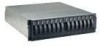
For information about installing and replacing hard disk drives, see "Installing a hot-swap hard disk drive" on page 38 and "Replacing a hot-swap hard disk drive" on page 39. For more information about the LEDs, see "Front view" on page 24. Rear view The following sections show the LEDs, controls, and connectors on the components at the rear of the storage subsystem. Power supply: The following illustration shows the LEDs, controls, and connectors on the power supply. Power OK LED Fault LED AC power connector AC power switch Figure 15. DS400 power supply LEDs, controls, and connectors Power cord connector Connect the power cord to this connector. AC power on/off switch Use this switch to turn the power supply on and off. Power OK LED (green) When this LED is lit, it indicates that the power supply is turned on. Fault LED (amber) When this LED is lit, there is a fault with either the power supply or a fan. Fibre Channel RAID controller: The Fibre Channel RAID controller has 12 LEDs and several connectors, depending on the storage subsystem model. The following illustration shows the LEDs and connectors on the DS400 storage subsystem Fibre Channel RAID controller. Chapter 3. IBM TotalStorage DS400 type 1700 (models 1RS, 2RD) storage subsystem 25
-
 1
1 -
2
-
3
-
4
-
5
-
6
-
7
-
8
-
9
-
10
-
11
-
12
-
13
-
14
-
15
-
16
-
17
-
18
-
19
-
20
-
21
-
22
-
23
-
24
-
25
-
26
-
27
-
28
-
29
-
30
-
31
-
32
-
33
-
 34
34 -
 35
35 -
 36
36 -
 37
37 -
 38
38 -
 39
39 -
 40
40 -
 41
41 -
 42
42 -
 43
43 -
 44
44 -
45
-
46
-
47
-
48
-
49
-
50
-
51
-
52
-
53
-
54
-
55
-
56
-
57
-
58
-
59
-
60
-
61
-
62
-
63
-
64
-
65
-
66
-
67
-
68
-
69
-
70
-
71
-
72
-
73
-
74
-
75
-
76
-
77
-
78
-
79
-
80
-
81
-
82
 |
 |
