IBM 17011RS Maintenance Manual - Page 21
Front
 |
UPC - 000435304971
View all IBM 17011RS manuals
Add to My Manuals
Save this manual to your list of manuals |
Page 21 highlights
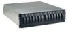
Front view The following illustration shows the components and controls on the front of the DS300 type 1701 (models 1RS, 2RD) storage subsystem. Note: The illustrations in this document might differ slightly from your hardware. Hard disk drive Drive filler panel Figure 1. DS300 (type 1701 (models 1RS, 2RD) storage subsystem front components Hard disk drive You can install up to 14 Ultra320 hot-swap hard disk drive customer replaceable units (CRUs) in the storage subsystem. Each hard disk drive CRU contains a hard disk drive and tray. Drive filler panel The storage subsystem comes without installed hard disk drives and contains filler panels in the unused drive bays. Before installing new drives, you must remove the filler panels and save them. Each of the 14 bays must always contain either a filler panel or a hard disk drive to maintain proper cooling and airflow. Tray handle and latch Use the blue latch on the tray handle to release or lock the hard disk drive in place. For information about installing and replacing a hard disk drive, see "Installing a hot-swap hard disk drive" on page 38 and "Replacing a hot-swap hard disk drive" on page 39. The following illustration shows the components and controls on the front of the DS300 (model 1RL) storage subsystem. Hard disk drive Side B Side A Figure 2. DS300 (model 1RL) storage subsystem front components Chapter 2. IBM TotalStorage DS300 storage subsystem type 1701 (models 1RL, 1RS, 2RD) 7
-
 1
1 -
2
-
3
-
4
-
5
-
6
-
7
-
8
-
9
-
10
-
11
-
12
-
13
-
14
-
15
-
 16
16 -
 17
17 -
 18
18 -
 19
19 -
 20
20 -
 21
21 -
 22
22 -
 23
23 -
 24
24 -
 25
25 -
 26
26 -
27
-
28
-
29
-
30
-
31
-
32
-
33
-
34
-
35
-
36
-
37
-
38
-
39
-
40
-
41
-
42
-
43
-
44
-
45
-
46
-
47
-
48
-
49
-
50
-
51
-
52
-
53
-
54
-
55
-
56
-
57
-
58
-
59
-
60
-
61
-
62
-
63
-
64
-
65
-
66
-
67
-
68
-
69
-
70
-
71
-
72
-
73
-
74
-
75
-
76
-
77
-
78
-
79
-
80
-
81
-
82
 |
 |
