IBM 865263Y Handbook - Page 21
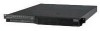
Back View, Universal Serial Bus USB connector 1
 |
View all IBM 865263Y manuals
Add to My Manuals
Save this manual to your list of manuals |
Page 21 highlights
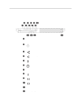
Back View Controls, indicators, and connectors 1 Power-on switch: Use this switch to turn on your server. 2 Ethernet 2 link indicator: This LED lights when there is an active link connection on the 10BASE-T or 100BASE-TX interface for Ethernet port 2. 3 Ethernet 1 link indicator: This LED lights when there is an active link connection on the 10BASE-T or 100BASE-TX interface for Ethernet port 1. 4 Ethernet connector 1: An unshielded, twisted-pair cable with an RJ-45 connector attaches here to the 10/100 Ethernet controller on the system board. 5 Ethernet connector 2: An unshielded, twisted-pair cable with an RJ-45 connector attaches here to the 10/100 Ethernet controller on the system board. 6 Ethernet 1 speed indicator: This LED lights when the speed of the Ethernet LAN connected to Ethernet port 1 is 100 Mbps. 7 Ethernet 2 speed indicator: This LED lights when the speed of the Ethernet LAN connected to Ethernet port 2 is 100 Mbps. 8 Universal Serial Bus (USB) connector 1: Reserved. 9 Universal Serial Bus (USB) connector 2: Reserved. 1 PCI slot 1: This slot contains the SCSI controller for the hard disk drives. You can connect an IBM-approved external tape drive to the connector on the SCSI adapter. See the Server-Proven list on http://www.ibm.com/compat/ to locate external tape drives. 11 PCI slot 2: This half-length slot can contain a second PCI adapter. Which adapter is present, if any, depends upon which server model you have. 12 Serial connector A: Signal cables for modems or other serial devices connect here to the 9-pin serial connector for serial port A. You might need to use a cable that has minimal bulk on its connector. 13 Serial connector B: Signal cables for modems or other serial devices connect here to the 9-pin serial connector for serial port B. You might need to use a cable that has minimal bulk on its connector. 14 Console bus connector (Out): Reserved. 15 Console bus connector (In): Use the console bus cable to connect the console bus connector (In) to the console adapter. See step 4 on page 19 for details. Chapter 1. Introducing your IBM Netfinity 4000R 11
-
 1
1 -
2
-
3
-
4
-
5
-
6
-
7
-
8
-
9
-
10
-
11
-
12
-
13
-
14
-
15
-
 16
16 -
 17
17 -
 18
18 -
 19
19 -
 20
20 -
 21
21 -
 22
22 -
 23
23 -
 24
24 -
 25
25 -
 26
26 -
27
-
28
-
29
-
30
-
31
-
32
-
33
-
34
-
35
-
36
-
37
-
38
-
39
-
40
-
41
-
42
-
43
-
44
-
45
-
46
-
47
-
48
-
49
-
50
-
51
-
52
-
53
-
54
-
55
-
56
-
57
-
58
-
59
-
60
-
61
-
62
-
63
-
64
-
65
-
66
-
67
-
68
-
69
-
70
-
71
-
72
-
73
-
74
-
75
-
76
-
77
-
78
-
79
-
80
-
81
-
82
-
83
-
84
-
85
-
86
-
87
-
88
-
89
-
90
-
91
-
92
-
93
-
94
-
95
-
96
-
97
-
98
-
99
-
100
-
101
-
102
 |
 |
