IBM SAN40B-4 User Guide - Page 33
Installing, switch, cabinet, required, Items
 |
UPC - 883436031479
View all IBM SAN40B-4 manuals
Add to My Manuals
Save this manual to your list of manuals |
Page 33 highlights
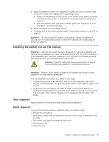
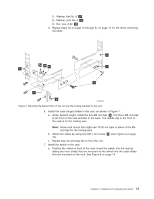
2. Apply the adhesive rubber feet. Applying the rubber feet onto the switch helps prevent the switch from sliding off the supporting surface. a. Clean the indentations at each corner of the bottom of the switch to ensure that they are free of dust or other debris that might lessen the adhesion of the feet. b. With the adhesive side against the chassis, place one rubber foot in each indentation and press into place. 3. Place the switch on a flat, sturdy surface. 4. Provide power to the switch as described in "Powering the switch on and off" on page 21. Attention: Do not connect the switch to the network until the IP address is correctly set. For instructions on how to set the IP address, see "Configuring the switch" on page 15. Installing the switch into an EIA cabinet Attention: Although the switch has been designed for customer installation and replacement procedures, you must first ensure that the rack into which the switch is to be installed is also customer accessible. If it is not, then only trained personnel can install and service these switches in such a rack. Attention: Read the "Safety and environmental notices" on page ix before attempting any installation or maintenance procedures. Attention: Refer to "Rack safety" on page xiv for danger and caution notices related to rack and cabinet installations. You can install the rack mount kit in either of two ways: v To allow the port side of the switch to slide out of the exhaust-air side of the cabinet. In this installation, the port side of the switch is flush with the edge of the cabinet. v To allow the non-port side of the switch to slide out the cool-air side of the cabinet. In this installation, the port side of the switch is set 7.62 cm (3 in.) back from the edge of the cabinet, allowing a more gradual bend in the fiber optic cables. Time required Approximately 30 minutes, excluding cabling and configuration Items required You need the following items to install the switch in a slide-rail rack: v Straight slot screwdriver v Rack space: 1 EIA units of rack space, 48.3 cm (19 in.) wide, and 60.96 cm (24 in.) deep v One power cord that is provided with the switch v One power outlet v Rack mount kit Chapter 2. Installing and configuring the switch 9
-
 1
1 -
2
-
3
-
4
-
5
-
6
-
7
-
8
-
9
-
10
-
11
-
12
-
13
-
14
-
15
-
16
-
17
-
18
-
19
-
20
-
21
-
22
-
23
-
24
-
25
-
26
-
27
-
 28
28 -
 29
29 -
 30
30 -
 31
31 -
 32
32 -
 33
33 -
 34
34 -
 35
35 -
 36
36 -
 37
37 -
 38
38 -
39
-
40
-
41
-
42
-
43
-
44
-
45
-
46
-
47
-
48
-
49
-
50
-
51
-
52
-
53
-
54
-
55
-
56
-
57
-
58
-
59
-
60
-
61
-
62
-
63
-
64
-
65
-
66
-
67
-
68
-
69
-
70
-
71
-
72
-
73
-
74
-
75
-
76
-
77
-
78
-
79
 |
 |
