IBM SAN40B-4 User Guide - Page 51
Description
 |
UPC - 883436031479
View all IBM SAN40B-4 manuals
Add to My Manuals
Save this manual to your list of manuals |
Page 51 highlights
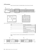
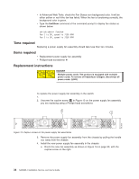
Note: Each SFP has a 10-pad gold-plated PCB-edge connector on the bottom. The correct position to insert an SFP into the upper row of ports is with the gold edge down. The correct position to insert an SFP into the lower row of ports is with the gold edge up. 2. Slide the SFP into the port until you feel it click into place; then close the bail. 1 A B C 2 ! A D B24_0004 Figure 11. SFP installation and bail closing Item A B C Description Switch chassis SFP with open bale SFP Chapter 3. Operating the switch 27
-
 1
1 -
2
-
3
-
4
-
5
-
6
-
7
-
8
-
9
-
10
-
11
-
12
-
13
-
14
-
15
-
16
-
17
-
18
-
19
-
20
-
21
-
22
-
23
-
24
-
25
-
26
-
27
-
28
-
29
-
30
-
31
-
32
-
33
-
34
-
35
-
36
-
37
-
38
-
39
-
40
-
41
-
42
-
43
-
44
-
45
-
 46
46 -
 47
47 -
 48
48 -
 49
49 -
 50
50 -
 51
51 -
 52
52 -
 53
53 -
 54
54 -
 55
55 -
 56
56 -
57
-
58
-
59
-
60
-
61
-
62
-
63
-
64
-
65
-
66
-
67
-
68
-
69
-
70
-
71
-
72
-
73
-
74
-
75
-
76
-
77
-
78
-
79
 |
 |

Note:
Each
SFP
has
a
10-pad
gold-plated
PCB-edge
connector
on
the
bottom.
The
correct
position
to
insert
an
SFP
into
the
upper
row
of
ports
is
with
the
gold
edge
down.
The
correct
position
to
insert
an
SFP
into
the
lower
row
of
ports
is
with
the
gold
edge
up.
2.
Slide
the
SFP
into
the
port
until
you
feel
it
click
into
place;
then
close
the
bail.
Item
Description
A
Switch
chassis
B
SFP
with
open
bale
C
SFP
1
2
A
A
D
B
C
!
B24_0004
Figure
11.
SFP
installation
and
bail
closing
Chapter
3.
Operating
the
switch
27