IBM SAN40B-4 User Guide - Page 45
Operating, switch
 |
UPC - 883436031479
View all IBM SAN40B-4 manuals
Add to My Manuals
Save this manual to your list of manuals |
Page 45 highlights
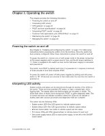
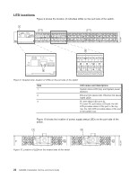
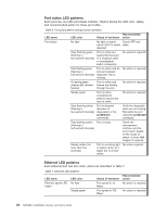
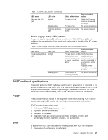
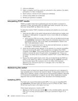
Chapter 3. Operating the switch This chapter provides the following information: v "Powering the switch on and off" v "Interpreting LED activity" v "LED patterns" on page 23 v "POST and boot specifications" on page 25 v "Interpreting POST results" on page 26 v "Customer field replaceable units (CRUs/FRUs)" on page 31 v "Maintaining the switch" on page 26 v "Managing the switch" on page 33 v Powering the switch on and off See Chapter 2, "Installing and configuring the switch," on page 7 for initial setup instructions before powering the switch on for the first time. Once the switch has been properly configured, follow these instructions to power the switch on and off. To power the switch on, connect one or both power cords to the power connectors on the power supplies and to a power source; then, set the AC power switches to ″|″. Power is supplied to the switch as soon as the first power supply is connected and powered on. The switch runs POST by default each time it is powered on; it requires a minimum of three minutes to boot and complete POST. To power the switch off, power off both power supplies by setting each AC power switch to ″O″. All devices are returned to their initial state the next time the switch is powered on. Interpreting LED activity System activity and status can be determined through the activity of the LEDs on the switch. There are three possible LED states: no light, a steady light, and a flashing light. The steady lights and flashing lights can be green or amber. The LEDs flash either of these colors during boot, POST, or other diagnostic tests. This is normal and does not indicate a problem unless the LEDs do not indicate a healthy state after all boot processes and diagnostic tests are complete. The switch has the following LEDs: v System power LED-One LED (green) to indicate system power v System status LED-One LED (green/amber) to indicate system status v Ethernet status LEDs-Two LEDs to indicate speed and link status v Port status LEDs-40 LEDs (green/amber) to indicate status for each port v One power supply status LED on each power supply, to the left of the ON/OFF rocker switch © Copyright IBM Corp. 2008 21
-
 1
1 -
2
-
3
-
4
-
5
-
6
-
7
-
8
-
9
-
10
-
11
-
12
-
13
-
14
-
15
-
16
-
17
-
18
-
19
-
20
-
21
-
22
-
23
-
24
-
25
-
26
-
27
-
28
-
29
-
30
-
31
-
32
-
33
-
34
-
35
-
36
-
37
-
38
-
39
-
 40
40 -
 41
41 -
 42
42 -
 43
43 -
 44
44 -
 45
45 -
 46
46 -
 47
47 -
 48
48 -
 49
49 -
 50
50 -
51
-
52
-
53
-
54
-
55
-
56
-
57
-
58
-
59
-
60
-
61
-
62
-
63
-
64
-
65
-
66
-
67
-
68
-
69
-
70
-
71
-
72
-
73
-
74
-
75
-
76
-
77
-
78
-
79
 |
 |