IBM SAN40B-4 User Guide - Page 36
mount
 |
UPC - 883436031479
View all IBM SAN40B-4 manuals
Add to My Manuals
Save this manual to your list of manuals |
Page 36 highlights
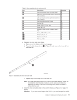
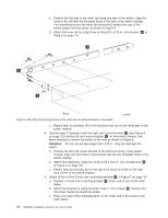
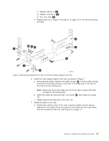
a. Position the flat side of the inner rail along one side of the switch. Align the holes in the rail with the threaded holes in the side of the switch chassis. The chamfered end of the inner rail should face toward the rear of the switch (away from the ports) as shown in Figure 6. b. Attach the inner rail by using three of the 8-32 x 3/16 in. zinc screws ( 6 in Table 3 on page 11). 1 6 3 Front Figure 6. Mounting the moving portion of the slide and mounting brackets to the switch SJ000047 c. Repeat step 3a and step 3b for the second inner rail on the other side of the switch chassis. 4. Optional step: If desired, install the right rack mount bracket 2 (see Figure 4 on page 10) and the left rack mount bracket 3 on the switch chassis. Use these brackets to secure the switch to the rack as shown in Figure 6. Attention: Do not use screws longer than 3/16 in.; they can damage the switch. a. Position the left rack mount bracket at the left front corner of the switch chassis. Align the two holes in the bracket with the two threaded holes in the switch chassis. b. Attach the bracket by using two of the 8-32 x 3/16 in. zinc screws (see 6 in Figure 4 on page 10) c. Repeat step 4a and step 4b for the right rack mount bracket on the right front corner of the switch chassis. 5. Attach all four of the 3-hole rack mounting brackets 4 in Figure 7 on page 13. a. Position a 3-hole rack mounting bracket 4 at the end of one of the outer slides. b. Attach the bracket by using the 8-32 x 3/8 in. zinc screws 9 . Ensure that the screw heads are inside the slides. c. Place one each of the following items on the outer end of the screw in the order listed: 12 SAN40B-4 Installation, Service, and User's Guide
-
 1
1 -
2
-
3
-
4
-
5
-
6
-
7
-
8
-
9
-
10
-
11
-
12
-
13
-
14
-
15
-
16
-
17
-
18
-
19
-
20
-
21
-
22
-
23
-
24
-
25
-
26
-
27
-
28
-
29
-
30
-
 31
31 -
 32
32 -
 33
33 -
 34
34 -
 35
35 -
 36
36 -
 37
37 -
 38
38 -
 39
39 -
 40
40 -
 41
41 -
42
-
43
-
44
-
45
-
46
-
47
-
48
-
49
-
50
-
51
-
52
-
53
-
54
-
55
-
56
-
57
-
58
-
59
-
60
-
61
-
62
-
63
-
64
-
65
-
66
-
67
-
68
-
69
-
70
-
71
-
72
-
73
-
74
-
75
-
76
-
77
-
78
-
79
 |
 |
