IBM SAN40B-4 User Guide - Page 47
patterns
 |
UPC - 883436031479
View all IBM SAN40B-4 manuals
Add to My Manuals
Save this manual to your list of manuals |
Page 47 highlights
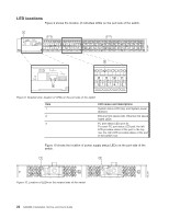
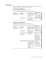
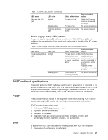
LED patterns Table 4 through Table 7 on page 24 summarize the switch LED locations, color, and meaning, as well as any recommended user response. Power status LED patterns The power status LED patterns are shown in Table 4 Table 4. Power status LED patterns, status, and recommended actions LED name LED color Recommended Status of hardware action Power Status LED No light System is off or there is an internal power supply failure. Verify the system is on. If the system is on, the unit is faulty. Contact IBM Support. Steady green Switch is on and power supplies are functioning properly. No action is required. System status LED patterns The system status LED patterns are shown in Table 5 Table 5. System status LED patterns, status, and recommended actions LED name LED color Recommended Status of hardware action System Status LED No light Switch is off, boot is Verify that switch is not complete, or boot on and has failed. completed booting. Steady green System is on and No action is required. functioning properly. Steady amber (for more than five seconds) Boot failed, the system is faulty. Perform the following steps: Connect a serial cable to the system. Reboot the system. Check the failure indicated on the system console. Contact IBM Support. Flashing amber/green Attention is required. Check the A number of variables management can cause this status interface and the including a single error log for details power supply failure, on the cause of a fan failure, or one status. Contact IBM or more Support if required. environmental ranges exceeded. Chapter 3. Operating the switch 23
-
 1
1 -
2
-
3
-
4
-
5
-
6
-
7
-
8
-
9
-
10
-
11
-
12
-
13
-
14
-
15
-
16
-
17
-
18
-
19
-
20
-
21
-
22
-
23
-
24
-
25
-
26
-
27
-
28
-
29
-
30
-
31
-
32
-
33
-
34
-
35
-
36
-
37
-
38
-
39
-
40
-
41
-
 42
42 -
 43
43 -
 44
44 -
 45
45 -
 46
46 -
 47
47 -
 48
48 -
 49
49 -
 50
50 -
 51
51 -
 52
52 -
53
-
54
-
55
-
56
-
57
-
58
-
59
-
60
-
61
-
62
-
63
-
64
-
65
-
66
-
67
-
68
-
69
-
70
-
71
-
72
-
73
-
74
-
75
-
76
-
77
-
78
-
79
 |
 |
