IBM SAN40B-4 User Guide - Page 49
specifications
 |
UPC - 883436031479
View all IBM SAN40B-4 manuals
Add to My Manuals
Save this manual to your list of manuals |
Page 49 highlights
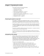
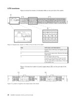
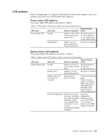
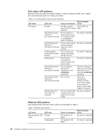
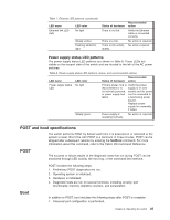
Table 7. Ethernet LED patterns (continued) LED name Ethernet link LED (left) LED color No light Steady amber Flashing amber/no light Status of hardware There is no link. There is a link. There is link activity (traffic). Recommended action Verify the Ethernet cable is connected correctly. No action is required. No action required. Power supply status LED patterns The power supply status LED patterns are shown in Table 8. These LEDs are visible on the nonport side of the switch and are located to the left of the AC power switches. Table 8. Power supply status LED patterns, status, and recommended actions LED name LED color Recommended Status of hardware action Power supply status No light LED Primary power cord is Verify the power disconnected or is supply is on and not actively powered, seated and the power or power supply has cord is connected to failed. a functioning power source. Replace power supply fan assembly, if failed. Steady green Power supply is operating normally. No action is required. POST and boot specifications The switch performs POST by default each time it is powered on or rebooted or the system is reset. Boot time with POST is a minimum of three minutes. POST can be skipped after subsequent reboots by entering the fastBoot command. For more information about this command, refer to the Fabric OS Command Reference. POST The success or failure results of the diagnostic tests that run during POST can be monitored through LED activity, the error log, or the command line interface. POST includes the following steps: 1. Preliminary POST diagnostics are run. 2. Operating system is initialized. 3. Hardware is initialized. 4. Diagnostic tests are run on several functions, including circuitry, port functionality, memory, statistics counters, and serialization. Boot In addition to POST, boot includes the following steps after POST is complete: 1. Universal port configuration is performed. Chapter 3. Operating the switch 25
-
 1
1 -
2
-
3
-
4
-
5
-
6
-
7
-
8
-
9
-
10
-
11
-
12
-
13
-
14
-
15
-
16
-
17
-
18
-
19
-
20
-
21
-
22
-
23
-
24
-
25
-
26
-
27
-
28
-
29
-
30
-
31
-
32
-
33
-
34
-
35
-
36
-
37
-
38
-
39
-
40
-
41
-
42
-
43
-
 44
44 -
 45
45 -
 46
46 -
 47
47 -
 48
48 -
 49
49 -
 50
50 -
 51
51 -
 52
52 -
 53
53 -
 54
54 -
55
-
56
-
57
-
58
-
59
-
60
-
61
-
62
-
63
-
64
-
65
-
66
-
67
-
68
-
69
-
70
-
71
-
72
-
73
-
74
-
75
-
76
-
77
-
78
-
79
 |
 |
