IBM SAN40B-4 User Guide - Page 39
Configuring, switch, Using, EZSwitch, setup, optional, Providing, power - brocade
 |
UPC - 883436031479
View all IBM SAN40B-4 manuals
Add to My Manuals
Save this manual to your list of manuals |
Page 39 highlights
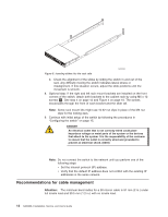
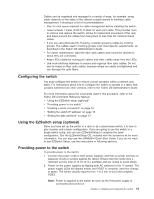
Cables can be organized and managed in a variety of ways: for example, using cable channels on the sides of the cabinet or patch panels to minimize cable management. Following is a list of recommendations: v Plan for rack space required for cable management before installing the switch. v Leave at least 1 meter (3.28 ft) of slack for each port cable. This provides room to remove and replace the switch, allows for inadvertent movement of the rack, and helps prevent the cables from being bent to less than the minimum bend radius. v If you are using Brocade ISL Trunking, consider grouping cables by trunking groups. The cables used in trunking groups must meet specific requirements, as described in the Fabric OS Administrator's Guide. v For easier maintenance, label the fiber optic cables and record the devices to which they are connected. v Keep LEDs visible by routing port cables and other cables away from the LEDs. v Use hook-and-loop fasteners to secure and organize fibre optic cables. Do not use tie wraps on fiber optic cables, because wraps are easily overtightened and can damage the optic fibers. Configuring the switch You must configure the switch to ensure correct operation within a network and fabric. For instructions about how to configure the switch to operate in a fabric that contains switches from other vendors, refer to the Fabric OS Administrator's Guide. For more information about the commands used in this procedure, refer to the Fabric OS Command Reference Manual. v "Using the EZSwitch setup (optional)" v "Providing power to the switch" v "Creating a serial connection" on page 16 v "Setting the switch IP address" on page 16 v "Setting the date and time" on page 17 Using the EZSwitch setup (optional) Once you have set up the switch in a rack or as a stand-alone switch, it is time to give it power and a basic configuration. If you are going to use the switch in a single-switch setup, you can use EZSwitchSetup to complete the basic configuration. See the EZSwitchSetup CD, included with the accessory kit for more information. You can also use the SAN40B-4 Quick Start Guide. If you do not want to use EZSwitch Setup, use the instructions in following sections. Providing power to the switch To provide power to the switch: 1. Connect the power cords to both power supplies, and then to power sources on separate circuits to protect against AC failure. Ensure that the cords have a minimum service loop of 15 cm (6 in.) available and are routed to avoid stress. 2. Power on the power supplies by flipping both AC switches to the "|" symbol. The power supply LEDs will display amber until POST is complete, and then change to green. The switch usually requires from 1 to 3 min to boot and complete POST. Note: Power is supplied to the switch as soon as the first power supply is connected and turned on. Chapter 2. Installing and configuring the switch 15
-
 1
1 -
2
-
3
-
4
-
5
-
6
-
7
-
8
-
9
-
10
-
11
-
12
-
13
-
14
-
15
-
16
-
17
-
18
-
19
-
20
-
21
-
22
-
23
-
24
-
25
-
26
-
27
-
28
-
29
-
30
-
31
-
32
-
33
-
 34
34 -
 35
35 -
 36
36 -
 37
37 -
 38
38 -
 39
39 -
 40
40 -
 41
41 -
 42
42 -
 43
43 -
 44
44 -
45
-
46
-
47
-
48
-
49
-
50
-
51
-
52
-
53
-
54
-
55
-
56
-
57
-
58
-
59
-
60
-
61
-
62
-
63
-
64
-
65
-
66
-
67
-
68
-
69
-
70
-
71
-
72
-
73
-
74
-
75
-
76
-
77
-
78
-
79
 |
 |