IBM SAN40B-4 User Guide - Page 34
Installation, instructions
 |
UPC - 883436031479
View all IBM SAN40B-4 manuals
Add to My Manuals
Save this manual to your list of manuals |
Page 34 highlights
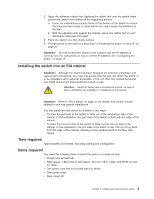
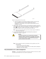
Attention: Use the exact screws specified in the procedure for use with the switch chassis. Using screws longer than 3/16 in. can damage the switch. The different types of screws are listed in Table 3 on page 11. Note: Make sure that you tighten all screws used in this procedure. Installation instructions To install the switch in a slide-rail rack that meets EIA standards, use the following procedure. Note: These procedures use parts that are included in the rack-mount kit. These parts are listed in Table 3 on page 11. The installation procedure cross-references the items in this table. Be sure to use the referenced parts when you perform each step. Before you start the rack-mount installation process, locate the rack-mount slides and the mounting bracket that are provided in the shipping container. Figure 4 shows the rack assembly. The number keys, such as 1 , refer to the items listed in Table 3 on page 11. 4 4X EIA Rack Rail Outer Slide 9 8X 7 4X Inner Slide See 1 Detail A 2X 3 Front of Switch 7 2 2X Figure 4. Rack assembly 7 4X 6 5X 6 2X 5 4X 10 8X 11 8X 12 8X Detail A SJ000153 1. Unpack the rack-mount kit and verify that all ordered items and parts are present and undamaged. See Table 3 on page 11 for a list of parts and the quantities supplied. 10 SAN40B-4 Installation, Service, and User's Guide
-
 1
1 -
2
-
3
-
4
-
5
-
6
-
7
-
8
-
9
-
10
-
11
-
12
-
13
-
14
-
15
-
16
-
17
-
18
-
19
-
20
-
21
-
22
-
23
-
24
-
25
-
26
-
27
-
28
-
 29
29 -
 30
30 -
 31
31 -
 32
32 -
 33
33 -
 34
34 -
 35
35 -
 36
36 -
 37
37 -
 38
38 -
 39
39 -
40
-
41
-
42
-
43
-
44
-
45
-
46
-
47
-
48
-
49
-
50
-
51
-
52
-
53
-
54
-
55
-
56
-
57
-
58
-
59
-
60
-
61
-
62
-
63
-
64
-
65
-
66
-
67
-
68
-
69
-
70
-
71
-
72
-
73
-
74
-
75
-
76
-
77
-
78
-
79
 |
 |
