IBM SAN40B-4 User Guide - Page 60
Environmental, requirements
 |
UPC - 883436031479
View all IBM SAN40B-4 manuals
Add to My Manuals
Save this manual to your list of manuals |
Page 60 highlights
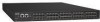
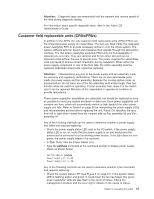
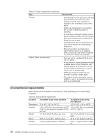
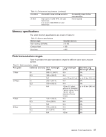
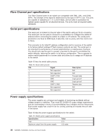
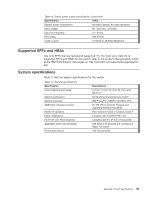
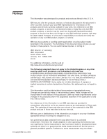
Table 11. Facility requirements (continued) Type Thermal Cabinet (when rack-mounted) Requirements v Air flows from the non-port side to the port side. A minimum air flow of 47 cubic feet/minute (79.8 cubic meters/hour) available in the immediate vicinity of the switch. v Ambient air temperature not exceeding 40° C (104° F) while the switch is operating v At a minimum, adequate cooling requires that you install the switch with the nonport side, which contains the air intake vents, facing the cool-air aisle v All equipment in the rack should force air in the same direction to avoid intaking exhaust air v Ensure that airflow and temperature requirements are met on an ongoing basis, particularly if the switch is installed in a closed or multicabinet assembly v One rack unit in a standard EIA 48.3 cm (19-in.) cabinet v All equipment in cabinet grounded through a reliable branch circuit connection and maintain ground at all times. Do not rely on a secondary connection to a branch circuit, such as a power strip v Additional weight of switch must not exceed the cabinet's weight limits v The cabinet must be secured to ensure stability in case of unexpected movement, such as an earthquake Environmental requirements Table 12 lists the acceptable environment for both operating and nonoperating conditions. Table 12. Environmental requirements Condition Acceptable range during operation Acceptable range during non-operation Temperature 0° to 40° C (32° to 104° F) -25° to 70°C (-13° to 158°F) Humidity 10% to 85% RH noncondensing, at 40°C 10% to 90% RH noncondensing, (104° F), with maximum gradient of 10% at 70° C (158° F) per hour Altitude 0 to 3 km (9,842 ft) above sea level 0 to 12 km (39,370 ft) above sea level Shock 20 G, 6 ms duration, half sine wave 33 G, 11 ms duration, half sine Vibration 0.5 G, 0.4 grms random, 5-500 Hz 2.0 G, 1.1 grms random, 5-500 Hz 36 SAN40B-4 Installation, Service, and User's Guide
-
 1
1 -
2
-
3
-
4
-
5
-
6
-
7
-
8
-
9
-
10
-
11
-
12
-
13
-
14
-
15
-
16
-
17
-
18
-
19
-
20
-
21
-
22
-
23
-
24
-
25
-
26
-
27
-
28
-
29
-
30
-
31
-
32
-
33
-
34
-
35
-
36
-
37
-
38
-
39
-
40
-
41
-
42
-
43
-
44
-
45
-
46
-
47
-
48
-
49
-
50
-
51
-
52
-
53
-
54
-
 55
55 -
 56
56 -
 57
57 -
 58
58 -
 59
59 -
 60
60 -
 61
61 -
 62
62 -
 63
63 -
 64
64 -
 65
65 -
66
-
67
-
68
-
69
-
70
-
71
-
72
-
73
-
74
-
75
-
76
-
77
-
78
-
79
 |
 |