IBM SAN40B-4 User Guide - Page 46
locations
 |
UPC - 883436031479
View all IBM SAN40B-4 manuals
Add to My Manuals
Save this manual to your list of manuals |
Page 46 highlights
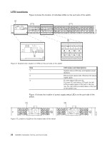
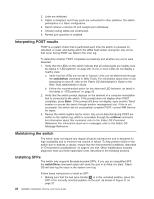
b40_0004 LED locations Figure 9 shows the location of individual LEDs on the port side of the switch. 1 0 123 4 567 8 9 10 11 12 13 14 15 16 17 18 19 20 21 22 23 24 25 26 27 28 29 30 31 32 33 34 35 36 37 38 39 3 8 9 10 11 2 12 13 14 15 Figure 9. Detailed view, location of LEDs on the port side of the switch Item 1 2 3 LED names and descriptions System status LED (top) and System power (bottom) Ethernet link status (left), Ethernet link speed (right) LEDs FC port status LED (port 9). For each FC port status LED pair, the left LED provides status of the port in the top row, the right LED provides status of the port in the bottom row. Figure 10 shows the location of power supply status LEDs on the port side of the switch. 1 2 b40_0005 Figure 10. Location of LEDs on the nonport side of the switch 22 SAN40B-4 Installation, Service, and User's Guide
-
 1
1 -
2
-
3
-
4
-
5
-
6
-
7
-
8
-
9
-
10
-
11
-
12
-
13
-
14
-
15
-
16
-
17
-
18
-
19
-
20
-
21
-
22
-
23
-
24
-
25
-
26
-
27
-
28
-
29
-
30
-
31
-
32
-
33
-
34
-
35
-
36
-
37
-
38
-
39
-
40
-
 41
41 -
 42
42 -
 43
43 -
 44
44 -
 45
45 -
 46
46 -
 47
47 -
 48
48 -
 49
49 -
 50
50 -
 51
51 -
52
-
53
-
54
-
55
-
56
-
57
-
58
-
59
-
60
-
61
-
62
-
63
-
64
-
65
-
66
-
67
-
68
-
69
-
70
-
71
-
72
-
73
-
74
-
75
-
76
-
77
-
78
-
79
 |
 |
