IBM SAN40B-4 User Guide - Page 62
Fibre, Channel, specifications, Serial, Power, supply - password recovery
 |
UPC - 883436031479
View all IBM SAN40B-4 manuals
Add to My Manuals
Save this manual to your list of manuals |
Page 62 highlights
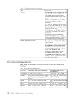
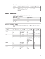
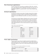
Fibre Channel port specifications The Fibre Channel ports in the switch are compatible with SWL, LWL, and ELWL SFPs. The strength of the signal is determined by the type of SFP in use. The ports are capable of operating at 1, 2, 4 and 8 Gbps, and are able to autosense the highest speed capable for all attached devices. The ports meet all required safety standards. Serial port specifications The serial port is located on the port side of the switch using an RJ-45 connector. The serial port can be used to connect to a workstation to configure the switch IP address before connecting the switch to a fabric or IP network. The serial port's parameters are fixed at 9600 baud, 8 data bits, and no parity, with flow control set to None. This connector is for initial IP address configuration and for recovery of the switch to its factory default settings if Flash memory contents are lost. The serial port is not intended for performance of normal administration or maintenance functions. You should only use this port to connect a terminal to the port to re-initialize the switch defaults, restoring the switch to its factory configuration. This is required to restore switch passwords to a known state and allow you to assign an IP address to the switch. Table 15 lists the serial cable pinouts. Table 15. Serial cable pinouts PIN Signal 1 Not supported 2 Not supported 3 UART1_TXD 4 GND 5 GND 6 UART1_RXD 7 Not supported 8 Not supported Description N/A N/A Transmit data Logic ground Logic ground Receive data N/A N/A Power supply specifications The power supplies are universal and capable of functioning worldwide without voltage jumpers or switches. They meet IEC 61000-4-5 surge voltage requirements and are autoranging in terms of accommodating input voltages and line frequencies. Each power supply has a built-in fan for cooling, pushing air towards the port side of the switch. Table 16 lists the power supply specifications for the switch. Table 16. Switch power supply specifications Specification Value Inlet C13 Maximum output from the power supply 125 watts 38 SAN40B-4 Installation, Service, and User's Guide
-
 1
1 -
2
-
3
-
4
-
5
-
6
-
7
-
8
-
9
-
10
-
11
-
12
-
13
-
14
-
15
-
16
-
17
-
18
-
19
-
20
-
21
-
22
-
23
-
24
-
25
-
26
-
27
-
28
-
29
-
30
-
31
-
32
-
33
-
34
-
35
-
36
-
37
-
38
-
39
-
40
-
41
-
42
-
43
-
44
-
45
-
46
-
47
-
48
-
49
-
50
-
51
-
52
-
53
-
54
-
55
-
56
-
 57
57 -
 58
58 -
 59
59 -
 60
60 -
 61
61 -
 62
62 -
 63
63 -
 64
64 -
 65
65 -
 66
66 -
 67
67 -
68
-
69
-
70
-
71
-
72
-
73
-
74
-
75
-
76
-
77
-
78
-
79
 |
 |
