IBM SAN40B-4 User Guide - Page 35
Attention
 |
UPC - 883436031479
View all IBM SAN40B-4 manuals
Add to My Manuals
Save this manual to your list of manuals |
Page 35 highlights
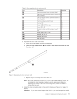
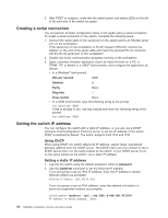
Table 3. Parts supplied with the rack-mount kit Item 1 Description Rack mount slide (inner and outer slide) Quantity 2 2 Right rack mount bracket (optional bracket for 1 front of switch) 3 Left rack mount bracket (optional bracket for 1 front of switch) 4 Rack mounting bracket (3-hole) 4 5 Nut clip, M5 11 6 Screw, 8-32 x 3/16 in., zinc 11 7 Screw, M5 x 12 11 8 Bracket to slide rack kit (contains items 9 - 1 12) 9 Screw, 8-32 x 3/8 in., zinc 5 10 Washer, flat, No. 8 5 11 Washer, lock, No. 8 5 12 Nut, hex, 8-32 5 2. Separate the inner and outer slides. a. Open one of the slides until the lock engages. b. Press the lock release lever ( 1 in Figure 5) and remove the inner rail from the outer rail. 1 Figure 5. Separating the inner and outer rails SJ000046 c. Repeat step 2a and step 2b for the other rail. Note: For racks with flush-mount doors, such as the 9306 Netfinity® racks, do not install the front brackets. Instead, use the rack-mount slides by attaching the switch to the set of mounting holes, which are offset 3 inches into the rack. 3. Install the inner (smaller) slide on the switch chassis, as Figure 4 on page 10 shows. Attention: If you use screws longer than 3/16 in., you can damage the switch. Chapter 2. Installing and configuring the switch 11
-
 1
1 -
2
-
3
-
4
-
5
-
6
-
7
-
8
-
9
-
10
-
11
-
12
-
13
-
14
-
15
-
16
-
17
-
18
-
19
-
20
-
21
-
22
-
23
-
24
-
25
-
26
-
27
-
28
-
29
-
 30
30 -
 31
31 -
 32
32 -
 33
33 -
 34
34 -
 35
35 -
 36
36 -
 37
37 -
 38
38 -
 39
39 -
 40
40 -
41
-
42
-
43
-
44
-
45
-
46
-
47
-
48
-
49
-
50
-
51
-
52
-
53
-
54
-
55
-
56
-
57
-
58
-
59
-
60
-
61
-
62
-
63
-
64
-
65
-
66
-
67
-
68
-
69
-
70
-
71
-
72
-
73
-
74
-
75
-
76
-
77
-
78
-
79
 |
 |
