IBM SAN40B-4 User Guide - Page 7
IBM SAN40B-4 - System Storage Switch Manual
 |
UPC - 883436031479
View all IBM SAN40B-4 manuals
Add to My Manuals
Save this manual to your list of manuals |
Page 7 highlights
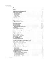
Figures 1. Port side of the switch 2 2. Fibre Channel port numbering 3 3. Non-port side of the switch 4 4. Rack assembly 10 5. Separating the inner and outer rails 11 6. Mounting the moving portion of the slide and mounting brackets to the switch 12 7. Mounting the fixed portion of the rail and the locking brackets to the rack 13 8. Inserting slides into the rack rails 14 9. Detailed view, location of LEDs on the port side of the switch 22 10. Location of LEDs on the nonport side of the switch 22 11. SFP installation and bail closing 27 12. Removing an SFP 29 13. Captive screws on the power supply fan assemblies 32 14. Installing a replacement power supply fan assembly 33 © Copyright IBM Corp. 2008 v
-
 1
1 -
 2
2 -
 3
3 -
 4
4 -
 5
5 -
 6
6 -
 7
7 -
 8
8 -
 9
9 -
 10
10 -
 11
11 -
 12
12 -
13
-
14
-
15
-
16
-
17
-
18
-
19
-
20
-
21
-
22
-
23
-
24
-
25
-
26
-
27
-
28
-
29
-
30
-
31
-
32
-
33
-
34
-
35
-
36
-
37
-
38
-
39
-
40
-
41
-
42
-
43
-
44
-
45
-
46
-
47
-
48
-
49
-
50
-
51
-
52
-
53
-
54
-
55
-
56
-
57
-
58
-
59
-
60
-
61
-
62
-
63
-
64
-
65
-
66
-
67
-
68
-
69
-
70
-
71
-
72
-
73
-
74
-
75
-
76
-
77
-
78
-
79
 |
 |

Figures
1.
Port
side
of
the
switch
.
.
.
.
.
.
.
.
.
.
.
.
.
.
.
.
.
.
.
.
.
.
.
.
.
.
.
.
.2
2.
Fibre
Channel
port
numbering
.
.
.
.
.
.
.
.
.
.
.
.
.
.
.
.
.
.
.
.
.
.
.
.
.
.3
3.
Non-port
side
of
the
switch
.
.
.
.
.
.
.
.
.
.
.
.
.
.
.
.
.
.
.
.
.
.
.
.
.
.
.4
4.
Rack
assembly
.
.
.
.
.
.
.
.
.
.
.
.
.
.
.
.
.
.
.
.
.
.
.
.
.
.
.
.
.
.
. 10
5.
Separating
the
inner
and
outer
rails
.
.
.
.
.
.
.
.
.
.
.
.
.
.
.
.
.
.
.
.
.
.
.
. 11
6.
Mounting
the
moving
portion
of
the
slide
and
mounting
brackets
to
the
switch
.
.
.
.
.
.
.
. 12
7.
Mounting
the
fixed
portion
of
the
rail
and
the
locking
brackets
to
the
rack
.
.
.
.
.
.
.
.
.
. 13
8.
Inserting
slides
into
the
rack
rails
.
.
.
.
.
.
.
.
.
.
.
.
.
.
.
.
.
.
.
.
.
.
.
.
. 14
9.
Detailed
view,
location
of
LEDs
on
the
port
side
of
the
switch
.
.
.
.
.
.
.
.
.
.
.
.
.
. 22
10.
Location
of
LEDs
on
the
nonport
side
of
the
switch
.
.
.
.
.
.
.
.
.
.
.
.
.
.
.
.
.
. 22
11.
SFP
installation
and
bail
closing
.
.
.
.
.
.
.
.
.
.
.
.
.
.
.
.
.
.
.
.
.
.
.
.
. 27
12.
Removing
an
SFP
.
.
.
.
.
.
.
.
.
.
.
.
.
.
.
.
.
.
.
.
.
.
.
.
.
.
.
.
.
. 29
13.
Captive
screws
on
the
power
supply
fan
assemblies
.
.
.
.
.
.
.
.
.
.
.
.
.
.
.
.
.
. 32
14.
Installing
a
replacement
power
supply
fan
assembly
.
.
.
.
.
.
.
.
.
.
.
.
.
.
.
.
.
. 33
©
Copyright
IBM
Corp.
2008
v