Intel S5520SC Service Guide - Page 16
Back Panel Features - amber
 |
UPC - 735858207522
View all Intel S5520SC manuals
Add to My Manuals
Save this manual to your list of manuals |
Page 16 highlights
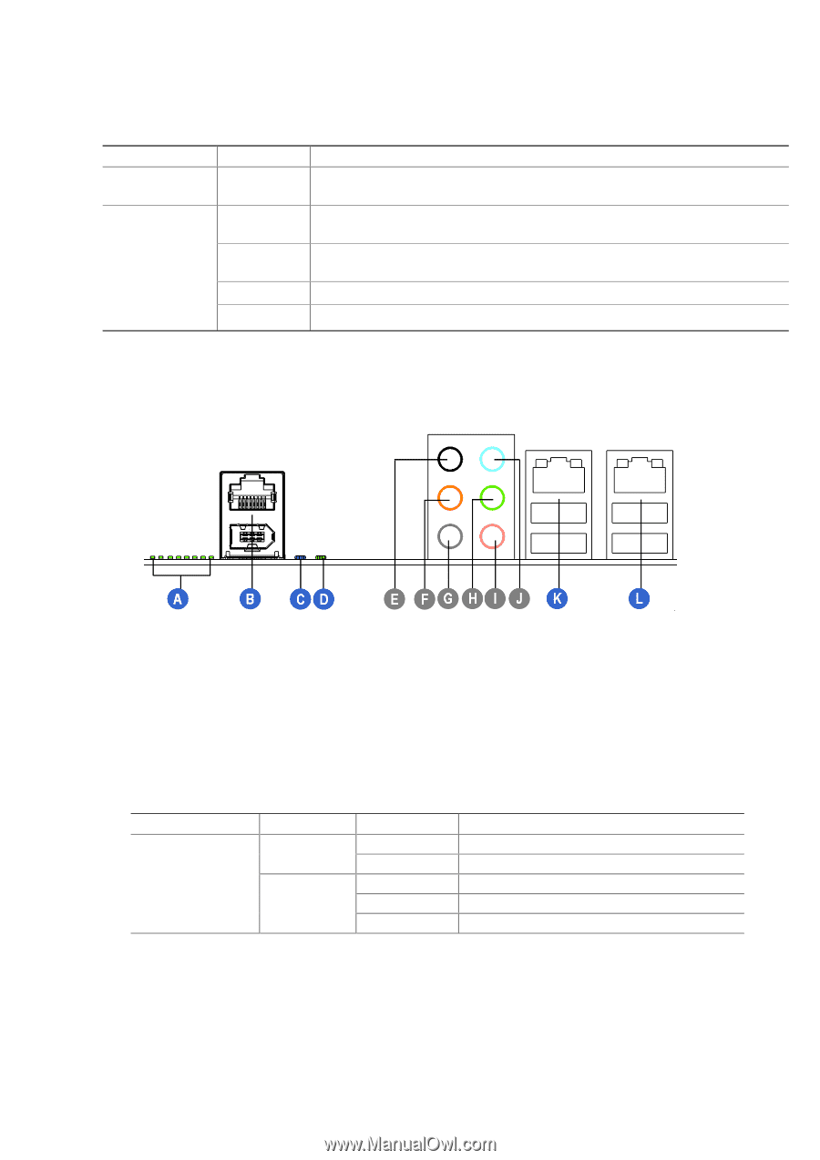
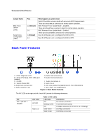
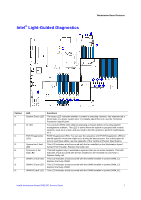
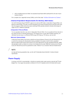
Workstation Board Features Jumper Name BMC Force Update (J1H1) Serial Port A Configuration (J4B2) Pins 1-2 (Default) 2-3 1-2(Default) 2-3 What happens at system reset from EFI-bootable recovery media with a recovery BIOS image present. These pin should not be connected for normal system operation. BMC Firmware Force Update Mode - Disabled. These pins should have a jumper in place for normal system operation. BMC Firmware Force Update Mode - Enabled. These pins should not be connected for normal operation. Rear RJ-45 Serial A port is configured for DSR to DTR. Rear RJ-45 Serial A port is configured for DCD to DTR. Back Panel Features A. POST Diagnostic LEDs G. Audio: side surround out B. Serial A Port (top), IEEE 1394a port (bottom) H. Audio: front surround out C. ID LED I. Audio: microphone in D. System Status LED J. Audio: line-in E. Audio: back surround out K. NIC 1 (top, default management port), Two USB (bottom) F. Audio: center/LFE out L. NIC 2 (top), Two USB (bottom) Figure 4. Back Panel Features The NIC LEDs at the right and left of each NIC provide the following information. NIC NIC 1 and NIC 2 (Gigabit) LED Color Left LED Right LED Table 3. NIC LEDs LED State Description Off No network connection Blinking Green Transmit/receive activity Off 10 Mbps connection (if left LED is on or blinking) Solid Green 100 Mbps connection Solid Amber 1000 Mbps connection 6 Intel® Workstation Board S5520SC Service Guide
-
 1
1 -
2
-
3
-
4
-
5
-
6
-
7
-
8
-
9
-
10
-
 11
11 -
 12
12 -
 13
13 -
 14
14 -
 15
15 -
 16
16 -
 17
17 -
 18
18 -
 19
19 -
 20
20 -
 21
21 -
22
-
23
-
24
-
25
-
26
-
27
-
28
-
29
-
30
-
31
-
32
-
33
-
34
-
35
-
36
-
37
-
38
-
39
-
40
-
41
-
42
-
43
-
44
-
45
-
46
-
47
-
48
-
49
-
50
-
51
-
52
-
53
-
54
-
55
-
56
-
57
-
58
-
59
-
60
-
61
-
62
-
63
 |
 |