Intel S5520SC Service Guide - Page 39
Replacing the Processor
 |
UPC - 735858207522
View all Intel S5520SC manuals
Add to My Manuals
Save this manual to your list of manuals |
Page 39 highlights
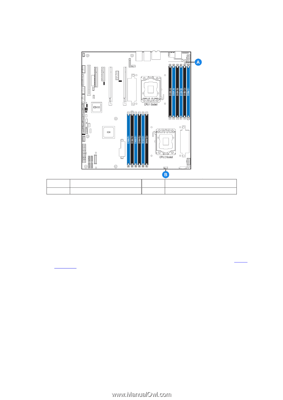
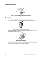
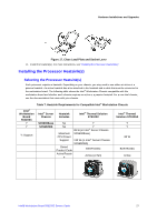
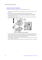
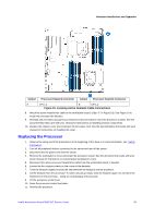
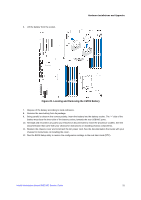
Hardware Installations and Upgrades Callout Processor Heatsink Connector Callout Processor Heatsink Connector A. CPU_1 B. CPU_2 Figure 19. Locating Active Heatsink Cable Connections 8. Attach the active heatsink fan cable to the workstation board. (Step "E" in Figure 18). See Figure 19 to locate the processor fan headers. 9. Reinstall and reconnect any parts you removed or disconnected to reach the processor sockets. See the documentation that came with your chassis for instructions on installing chassis components. 10. Replace the chassis cover and reconnect the AC power cord. See the documentation that came with your chassis for instructions on installing the cover. Replacing the Processor 1. Observe the safety and ESD precautions at the beginning of this book. For more information, see "Safety Information". 2. Turn off all peripheral devices connected to the server and turn off the server. 3. Disconnect the AC power cord from the server. 4. Remove the workstation's cover and locate the processor socket. See the document that came with your server chassis for instructions on removing the workstation's cover. 5. Disconnect the active processor heatsink fan cable from the workstation board, if needed. 6. Loosen the four captive screws on the corner of the heatsink. 7. Twist the heatsink slightly to break the seal between the heatsink and the processor. 8. Lift the heatsink from the processor. If it does not pull up easily, twist the heatsink again. Do not force the heatsink from the processor - doing so could damage the processor. 9. Lift the processor socket lever. 10. Raise the processor socket load plate. 11. Remove the processor. Intel® Workstation Board S5520SC Service Guide 29
-
 1
1 -
2
-
3
-
4
-
5
-
6
-
7
-
8
-
9
-
10
-
11
-
12
-
13
-
14
-
15
-
16
-
17
-
18
-
19
-
20
-
21
-
22
-
23
-
24
-
25
-
26
-
27
-
28
-
29
-
30
-
31
-
32
-
33
-
 34
34 -
 35
35 -
 36
36 -
 37
37 -
 38
38 -
 39
39 -
 40
40 -
 41
41 -
 42
42 -
 43
43 -
 44
44 -
45
-
46
-
47
-
48
-
49
-
50
-
51
-
52
-
53
-
54
-
55
-
56
-
57
-
58
-
59
-
60
-
61
-
62
-
63
 |
 |