Intel S5520SC Service Guide - Page 17
Intel, Light-Guided Diagnostics - system status led
 |
UPC - 735858207522
View all Intel S5520SC manuals
Add to My Manuals
Save this manual to your list of manuals |
Page 17 highlights
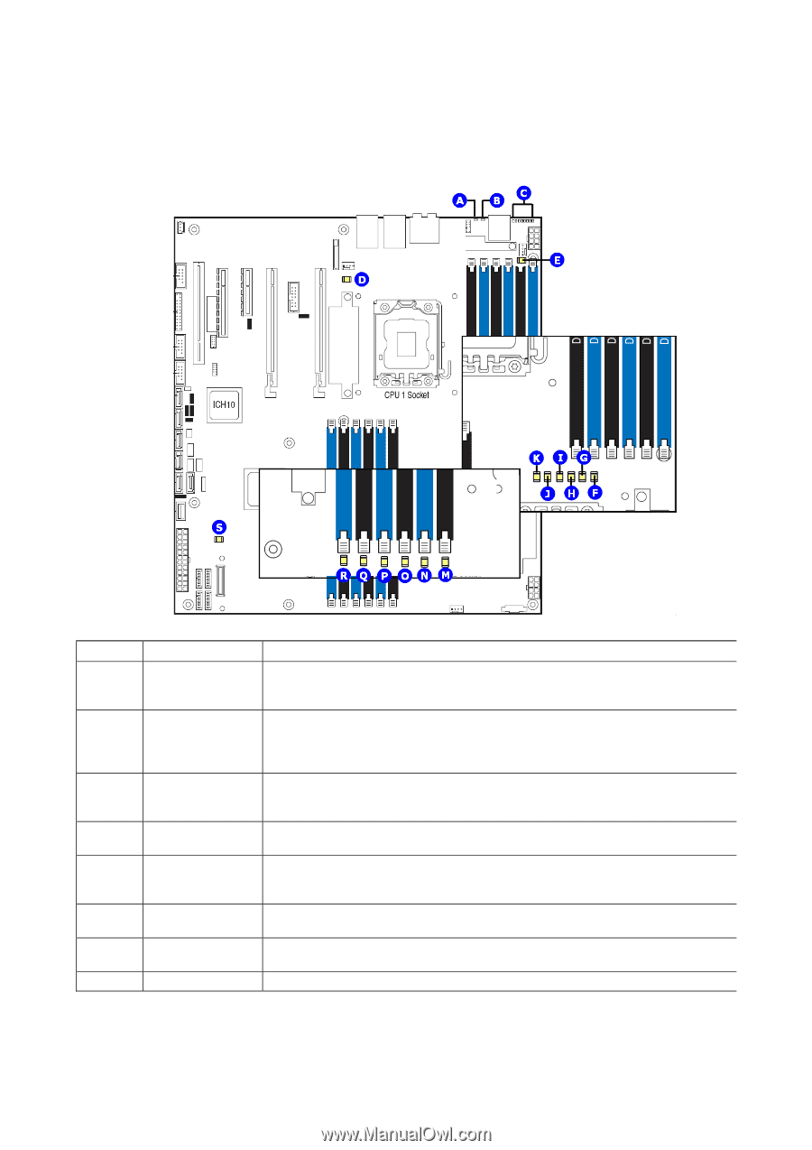
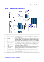
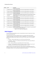
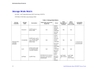
Intel® Light-Guided Diagnostics Workstation Board Features Callout A. B. C. D. E. F. G. H. LED System Status LED ID LED POST Diagnostics LEDs System fan 5 fault LED Processor 1 fan fault LED DIMM C1 fault LED DIMM C2 fault LED DIMM B1 fault LED Functions The status LED indicates whether a system is operating correctly, has experienced a minor fault, or a major system error. For details about this LED, see the Technical Production Specification. You can turn off this LED either by pressing a chassis button or by using system management software. This LED is useful when the system is grouped with several systems, such as in a rack, and you need to find the system to perform maintenance on it. POST Diagnostics LEDs: You can use the sequence of lit POST Diagnostics LEDs to identify specific errors that might occur during the boot process. For a description of how to read these LEDs, see the appendix of the Technical Product Specification. This LED indicates a fault occurred with the fan installed on the Workstation board System Fan 5 header. Replace the faulty unit. This LED applies only to workstation systems that use an active heatsink. This LED indicates a fault occurred with the fan installed on the heatsink for processor 1. Replace faulty unit. This LED indicates a fault occurred with the DIMM installed in socket DIMM_C1. Replace the faulty DIMM. This LED indicates a fault occurred with the DIMM installed in socket DIMM_C2. Replace the faulty DIMM. This LED indicates a fault occurred with the DIMM installed in socket DIMM_B1. Intel® Workstation Board S5520SC Service Guide 7
-
 1
1 -
2
-
3
-
4
-
5
-
6
-
7
-
8
-
9
-
10
-
11
-
 12
12 -
 13
13 -
 14
14 -
 15
15 -
 16
16 -
 17
17 -
 18
18 -
 19
19 -
 20
20 -
 21
21 -
 22
22 -
23
-
24
-
25
-
26
-
27
-
28
-
29
-
30
-
31
-
32
-
33
-
34
-
35
-
36
-
37
-
38
-
39
-
40
-
41
-
42
-
43
-
44
-
45
-
46
-
47
-
48
-
49
-
50
-
51
-
52
-
53
-
54
-
55
-
56
-
57
-
58
-
59
-
60
-
61
-
62
-
63
 |
 |