Intel S5520SC Service Guide - Page 36
Caution
 |
UPC - 735858207522
View all Intel S5520SC manuals
Add to My Manuals
Save this manual to your list of manuals |
Page 36 highlights
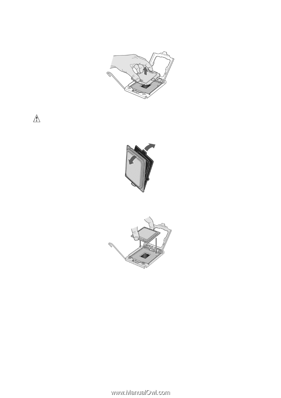
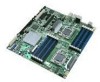
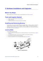
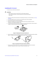
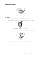
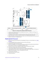
Hardware Installations and Upgrades Figure 14. Removing the Processor Socket Protective Cover CAUTION To avoid damage, DO NOT drop the cover onto the socket wires or components. 8. Take the processor out of the box and remove the protective shipping cover as shown in Figure 15. Figure 15. Remove Processor Protective Cover 9. Orient the processor with the socket so the processor cutouts match the two socket pins and then sit the processor into the socket as shown in Figure 16. Figure 16. Install the processor 10. Close the load plate and socket lever: Close the load plate all the way as shown in Figure 17 (Step "A"), push down on the load plate (Step "B" in Figure 17), and close the socket lever and ensure the load plate tab engages under the socket lever when fully closed (Step "C" in Figure 17). 26 Intel® Workstation Board S5520SC Service Guide
-
 1
1 -
2
-
3
-
4
-
5
-
6
-
7
-
8
-
9
-
10
-
11
-
12
-
13
-
14
-
15
-
16
-
17
-
18
-
19
-
20
-
21
-
22
-
23
-
24
-
25
-
26
-
27
-
28
-
29
-
30
-
 31
31 -
 32
32 -
 33
33 -
 34
34 -
 35
35 -
 36
36 -
 37
37 -
 38
38 -
 39
39 -
 40
40 -
 41
41 -
42
-
43
-
44
-
45
-
46
-
47
-
48
-
49
-
50
-
51
-
52
-
53
-
54
-
55
-
56
-
57
-
58
-
59
-
60
-
61
-
62
-
63
 |
 |