Invacare MVPS Owners Manual - Page 27
Installing Adjustable Angle Flip-up Footplate Hinge, Front Riggings
 |
View all Invacare MVPS manuals
Add to My Manuals
Save this manual to your list of manuals |
Page 27 highlights
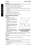
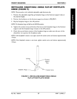
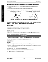
FRONT RIGGINGS FRONT RIGGINGS FRONT RIGGINGS SECTION 3 INSTALLING ADJUSTABLE ANGLE FLIP-UP FOOTPLATE HINGE (FIGURE 9) NOTE: This procedure is for individual adjustable angle footrests only. 1. Position the adjustable angle flip-up footplate hinge on the footrest support tube at the desired height. 2. Position the hardware on the footrest support as shown in FIGURE 9. 3. Flip the footplate hinge to the UP position. NOTE: The footplate hinge will fall to the DOWN position. 4. Tighten the socket screw and locknut that secure the footplate hinge to the footrest support until the footplate hinge remains in the UP position. 5. Check the up and down motion of the footplate hinge to make sure the user of the wheelchair can operate the footplates easily. NOTE: If the footplate's motion is too tight, loosen the socket screw and locknut approximately 1/4-turn. NOTE: If the footplate's motion is too loose, tighten socket screw and locknut approximately 1/4-turn. Locknut Footrest Support Tube Footplate Hinge Socket Screw FIGURE 9 - INSTALLING ADJUSTABLE ANGLE FLIP-UP FOOTPLATE HINGE Part No. 1106638 27 MVP™ & MVP jr.™
-
 1
1 -
2
-
3
-
4
-
5
-
6
-
7
-
8
-
9
-
10
-
11
-
12
-
13
-
14
-
15
-
16
-
17
-
18
-
19
-
20
-
21
-
 22
22 -
 23
23 -
 24
24 -
 25
25 -
 26
26 -
 27
27 -
 28
28 -
 29
29 -
 30
30 -
 31
31 -
 32
32 -
33
-
34
-
35
-
36
-
37
-
38
-
39
-
40
-
41
-
42
-
43
-
44
-
45
-
46
-
47
-
48
-
49
-
50
-
51
-
52
-
53
-
54
-
55
-
56
-
57
-
58
-
59
-
60
 |
 |
