Invacare MVPS Owners Manual - Page 34
adjusting the back angle - Square Rear Frame, DETAIL A - BACK, ANGLE MOUNTING, HOLES, UPPER, LOWER
 |
View all Invacare MVPS manuals
Add to My Manuals
Save this manual to your list of manuals |
Page 34 highlights
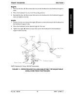
BACK SECTION 4 BACK ADJUSTING THE BACK ANGLE - SQUARE REAR FRAME (FIGURE 3) NOTE: This procedure applies to adjustable angle backs only. NOTE: The back adjusts to four (4) positions in five 5° degree increments from 0° to 15°. 1. Remove the two (2) back angle adjustment screws and locknuts. 2. Reposition the back to the desired angle. 3. Ensure the upper back angle mounting hole is aligned with one (1) of the four (4) upper angle adjustment holes. 4. Install one (1) of the back angle adjustment screws through the upper back angle mounting hole and the desired upper angle adjustment hole. 5. Install the remaining back angle adjustment screw through the lower back angle mounting hole and the desired lower angle adjustment hole. 6. Secure each back angle adjustment screw with a locknut. Torque locknut to 80-100 in/lbs. Back Cane Back Angle Adjustment Screw Locknut Upper Back Angle Mounting Hole Locknut Lower Back Angle Mounting Hole Back Angle Adjustment Screw DETAIL "A" - BACK ANGLE MOUNTING HOLES UPPER 0° 5° 10° 15° LOWER 15° 10° 5° 0° FIGURE 3 - ADJUSTING THE BACK ANGLE - SQUARE REAR FRAME MVP™ & MVP jr.™ 34 Part No. 1106638
-
 1
1 -
2
-
3
-
4
-
5
-
6
-
7
-
8
-
9
-
10
-
11
-
12
-
13
-
14
-
15
-
16
-
17
-
18
-
19
-
20
-
21
-
22
-
23
-
24
-
25
-
26
-
27
-
28
-
 29
29 -
 30
30 -
 31
31 -
 32
32 -
 33
33 -
 34
34 -
 35
35 -
 36
36 -
 37
37 -
 38
38 -
 39
39 -
40
-
41
-
42
-
43
-
44
-
45
-
46
-
47
-
48
-
49
-
50
-
51
-
52
-
53
-
54
-
55
-
56
-
57
-
58
-
59
-
60
 |
 |
