Invacare MVPS Owners Manual - Page 50
Using/installing/adjusting Cantilever Arms, Using Installing/adjusting
 |
View all Invacare MVPS manuals
Add to My Manuals
Save this manual to your list of manuals |
Page 50 highlights
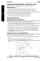
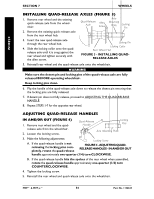
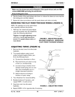
ARMS SECTION 6 ARMS USING/INSTALLING/ADJUSTING CANTILEVER ARMS NOTE: The cantilever arms are designed for use with the fixed height back canes only. USING (FIGURE 11) 1. Pull the actuator of the locking mechanism towards the front of the wheelchair. 2. While holding the actuator of the locking mechanism, pull up on the cantilever arm. NOTE: If necessary, the locking mechanism in the cantilever arm can be repositioned so the cantilever arm will open down instead of up. For this adjustment, contact a qualified technician. 3. To lock the cantilever arm, push down until there is an audible click. 4. Pull up on the cantilever arm to make sure it is locked in place. INSTALLING/ADJUSTING Installing Cantilever Arm (FIGURE 11). NOTE: When removing the locknuts and washers from the cantilever arm assembly, leave the top hex bolt, coved washers and spacer (between adjustment plate and cantilever arm) in place. 1. Slide the partially assembled cantilever arm assembly w/mounting hardware through the back cane. Make sure the adjustment plate is towards the inside of the wheelchair. NOTE: This includes top hex bolt, coved washers and spacer (between adjustment plate and cantilever arm). 2. Slide the bottom hex bolt (w/coved washer) through the adjustment plate and back cane. 3. Securely tighten the cantilever arm to the wheelchair with two (2) locknuts and washers. 4. Adjust the angle of the cantilever arm, if necessary. Refer to ADJUSTING CANTILEVER ARM ANGLE in this section of the manual. Adjusting Cantilever Arm Height (FIGURE 11). NOTE: When removing the locknuts and washers from the cantilever arm assembly, leave the top hex bolt, coved washers and spacer (between adjustment plate and cantilever arm) in place. 1. Remove the two (2) locknuts and washers securing the cantilever arm assembly to the back cane. 2. Remove the cantilever arm assembly with hardware from the back cane. 3. Perform STEPS 1-4 in INSTALLING CANTILEVER ARM to reposition the arm at the desired height. Adjustment Plate Coved Washers Back Cane Spacer Actuator Locknuts Washers Top Hex Bolt and Coved Washer Bottom Hex Bolt Cantilever Arm FIGURE 11- USING/INSTALLING/ADJUSTING CANTILEVER ARMS MVP™ & MVP jr.™ 50 Part No. 1106638
-
 1
1 -
2
-
3
-
4
-
5
-
6
-
7
-
8
-
9
-
10
-
11
-
12
-
13
-
14
-
15
-
16
-
17
-
18
-
19
-
20
-
21
-
22
-
23
-
24
-
25
-
26
-
27
-
28
-
29
-
30
-
31
-
32
-
33
-
34
-
35
-
36
-
37
-
38
-
39
-
40
-
41
-
42
-
43
-
44
-
 45
45 -
 46
46 -
 47
47 -
 48
48 -
 49
49 -
 50
50 -
 51
51 -
 52
52 -
 53
53 -
 54
54 -
 55
55 -
56
-
57
-
58
-
59
-
60
 |
 |
