Invacare MVPS Owners Manual - Page 57
Installing/adjusting The Anti-tippers
 |
View all Invacare MVPS manuals
Add to My Manuals
Save this manual to your list of manuals |
Page 57 highlights
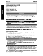
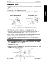
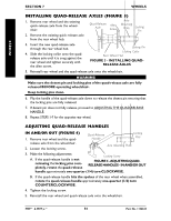
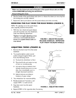
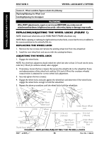
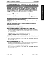
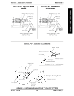
WHEEL LOCK/ANTI-TIPPERS WHEEL LOCK/ANTI-TIPPERS SECTION 8 INSTALLING/ADJUSTING THE ANTI-TIPPERS (FIGURE 2) WARNING Anti-tippers and sockets on wheelchairs manufactured on or after 10/28/02 ARE NOT compatible with older anti-tippers and sockets. If replacing the anti-tippers which originally came with the wheelchair, replace BOTH the anti-tipper AND the socket. Newer anti-tippers have black release buttons and the sockets are marked with an indentation as shown below: Indentation Indentation Anti-tippers MUST be fully engaged and release buttons fully protruding out of release button holes BEFORE using wheelchair. DO NOT install anti-tippers into rear step tubes of square and extended rear frames. Make sure the anti-tipper wheels are pointing towards the ground/floor BEFORE using the wheelchair. INSTALLING THE ANTI-TIPPERS Square and Extended Rear Frames (DETAILS "A" AND "B"). 1. Press the release buttons IN and insert the anti-tippers with the anti-tipper wheels pointing toward the ground/floor into the wheelchair frame until the two (2) locking pins are secured in the: SQUARE FRAME - FRONT mounting hole (DETAIL "A"). EXTENDED FRAME - REAR mounting hole (DETAIL "B"). NOTE: A 1-1/2 to 2-inch clearance between the bottom of the anti-tipper wheels and the ground/ floor must be maintained. 2. Adjust the anti-tipper height. Refer to ADJUSTING THE ANTI-TIPPER HEIGHT in this section of the manual. Curved Rear Frame (DETAIL "C"). 1. Press down on the release buttons of the anti-tipper and insert the anti-tipper into the anti-tipper mounting bracket until the release buttons lock in place. 2. Repeat STEPS 1-6 for the opposite side of the wheelchair. 3. Adjust the anti-tipper height. Refer to ADJUSTING THE ANTI-TIPPER HEIGHT in this section of the manual. Part No. 1106638 57 MVP™ & MVP jr.™
-
 1
1 -
2
-
3
-
4
-
5
-
6
-
7
-
8
-
9
-
10
-
11
-
12
-
13
-
14
-
15
-
16
-
17
-
18
-
19
-
20
-
21
-
22
-
23
-
24
-
25
-
26
-
27
-
28
-
29
-
30
-
31
-
32
-
33
-
34
-
35
-
36
-
37
-
38
-
39
-
40
-
41
-
42
-
43
-
44
-
45
-
46
-
47
-
48
-
49
-
50
-
51
-
 52
52 -
 53
53 -
 54
54 -
 55
55 -
 56
56 -
 57
57 -
 58
58 -
 59
59 -
 60
60
 |
 |