Konica Minolta PKG-675i PKG-675i User Manual - Page 74
Controls / Install Service Station Wiper
 |
View all Konica Minolta PKG-675i manuals
Add to My Manuals
Save this manual to your list of manuals |
Page 74 highlights
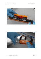
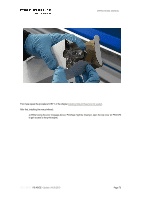
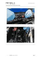
OPERATIONAL MANUAL Obtain a new MFR and remove the protective plastic cover by peeling along the MFR length at the perforated section of the covering. Soak the MFR with distilled water. Orient the MFR so that the end with the ratchet mounted to it is placed to the left. Starting at the left end of the Service Station carousel, place the left end of the MFR at the entrance to the holder. Note the position of the ratchet and white disk elements in middle figure below. Move the right end of the MFR into position as illustrated below. Note the position of the ratchet and white disk. Empty MFR Holder Left end of MFR at Entrance to Holder Right end of MFR at Entrance to Holder Push firmly downward on the MFR, inserting the two portions of the shaft into the spring- loaded holders. Test for the proper engagement of the MFR ratchets by attempting to rotate the MFR towards the media exit side of the printer. A moderate force should be enough to rotate the MFR in steps ("ratchet"). If it does not rotate, then remove the MFR and reseat it within the holders. Attempt to rotate the MFR backwards, towards the media entrance side of the Print Engine, by applying the same amount of force required to rotate it in the forward direction. If the MFR is installed properly, it should not rotate backwards. Press "Close Printhead" on the "Controls" of the User Interface. To finish the process, press "Install Service Station Wiper". Controls / Install Service Station Wiper DOCUMENT I 18.40V02 - Update: 04.09.2019 Page 74
-
 1
1 -
2
-
3
-
4
-
5
-
6
-
7
-
8
-
9
-
10
-
11
-
12
-
13
-
14
-
15
-
16
-
17
-
18
-
19
-
20
-
21
-
22
-
23
-
24
-
25
-
26
-
27
-
28
-
29
-
30
-
31
-
32
-
33
-
34
-
35
-
36
-
37
-
38
-
39
-
40
-
41
-
42
-
43
-
44
-
45
-
46
-
47
-
48
-
49
-
50
-
51
-
52
-
53
-
54
-
55
-
56
-
57
-
58
-
59
-
60
-
61
-
62
-
63
-
64
-
65
-
66
-
67
-
68
-
 69
69 -
 70
70 -
 71
71 -
 72
72 -
 73
73 -
 74
74 -
 75
75 -
 76
76 -
 77
77 -
 78
78 -
 79
79 -
80
-
81
-
82
-
83
-
84
-
85
-
86
-
87
-
88
-
89
-
90
-
91
-
92
-
93
-
94
-
95
-
96
-
97
-
98
-
99
-
100
-
101
-
102
-
103
-
104
-
105
-
106
-
107
-
108
-
109
-
110
-
111
-
112
-
113
-
114
-
115
-
116
-
117
-
118
 |
 |
