Lantronix IntelliBox-I/O IntelliBox-I/O - User Guide - Page 121
Input/Output Settings, Advanced Settings, IntelliBox-I/O 2100 User Guide
 |
View all Lantronix IntelliBox-I/O manuals
Add to My Manuals
Save this manual to your list of manuals |
Page 121 highlights
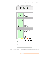
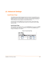
12: Advanced Settings Table 12-1 Input/Output Page Input/Output Page Settings Pin Direction Description Identifies the digital switch port and the relay. Select the direction of data flow. Choices are: Input = pin is set to read input Output = pin is set to drive data out of the IntelliBox . Output Controlled by The functions that control an output display in rows below the output. State Displays the state of an input or output pin. The state of an input pin, High or Low, depends on the external voltage sensed. When a pin is configured as ouput, it acts as a solid state switch and has a state of either Open or Closed. Initially the output is Open. The Output is Closed if just one controlling function is asserted Closed, such as in Tunnel1 Connect Mode. Control Select the output controls. Choices are: Normal = allows an output to be controlled normally by the configured device functions Force Closed = asserts the output as Closed regardless of the state of the device functions. For example, even if other functions within the IntelliBox have not changed the pin state, you can still force the output state closed manually. Force Open: asserts the output as Open regardless of the state of the device functions. For example, even if other functions within the IntelliBox have not changed the pin state, you can still force the output state closed manually. RSS Trace transitions A change in the state of a pin triggers the IntelliBox to send an RSS feed. Primarily used for troubleshooting. RSS Trace transitions are visible when XI01/XI02 are set to the Input option. Note: The Relay is an output port only. IntelliBox-I/O 2100 User Guide 121
-
 1
1 -
2
-
3
-
4
-
5
-
6
-
7
-
8
-
9
-
10
-
11
-
12
-
13
-
14
-
15
-
16
-
17
-
18
-
19
-
20
-
21
-
22
-
23
-
24
-
25
-
26
-
27
-
28
-
29
-
30
-
31
-
32
-
33
-
34
-
35
-
36
-
37
-
38
-
39
-
40
-
41
-
42
-
43
-
44
-
45
-
46
-
47
-
48
-
49
-
50
-
51
-
52
-
53
-
54
-
55
-
56
-
57
-
58
-
59
-
60
-
61
-
62
-
63
-
64
-
65
-
66
-
67
-
68
-
69
-
70
-
71
-
72
-
73
-
74
-
75
-
76
-
77
-
78
-
79
-
80
-
81
-
82
-
83
-
84
-
85
-
86
-
87
-
88
-
89
-
90
-
91
-
92
-
93
-
94
-
95
-
96
-
97
-
98
-
99
-
100
-
101
-
102
-
103
-
104
-
105
-
106
-
107
-
108
-
109
-
110
-
111
-
112
-
113
-
114
-
115
-
 116
116 -
 117
117 -
 118
118 -
 119
119 -
 120
120 -
 121
121 -
 122
122 -
 123
123 -
 124
124 -
 125
125 -
 126
126 -
127
-
128
-
129
-
130
-
131
-
132
-
133
-
134
-
135
-
136
-
137
-
138
-
139
-
140
-
141
-
142
-
143
-
144
-
145
-
146
-
147
-
148
-
149
-
150
-
151
-
152
-
153
-
154
-
155
-
156
-
157
-
158
-
159
-
160
-
161
-
162
-
163
-
164
-
165
-
166
-
167
-
168
-
169
-
170
-
171
-
172
-
173
-
174
-
175
-
176
-
177
-
178
-
179
-
180
-
181
-
182
-
183
-
184
-
185
-
186
-
187
-
188
-
189
-
190
 |
 |
