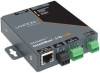
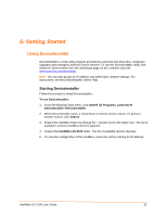
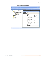
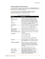
Lantronix IntelliBox-I/O IntelliBox-I/O - User Guide - Page 32
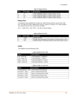
Relay Port, LEDs, Pin Name, Description
 |
View all Lantronix IntelliBox-I/O manuals
Add to My Manuals
Save this manual to your list of manuals |
Page 32 highlights
4: Installation Pin # 1 2 3 4 Pin Name 1+ 12+ 2- Table 4-4 Digital I/O Pins Description 2-wire configurable digital IO, positive contact, 1st port 2-wire configurable digital IO, negative contact, 1st port 2-wire configurable digital IO, positive contact, 2nd port 2-wire configurable digital IO, negative contact, 2nd port Relay Port A 3-terminal relay-controlled dry contact NC, COM, NO (up to 8A) is on the front of the unit. The relay is for SELV applications only (UL Class III or Class 2). The relay contacts are isolated from the inner circuit of the IntelliBox. Pin 1 = COM, PIN 2 = NO, PIN 3 = NC due to recent change Pin # 1 2 3 Pin Name COM NO NC Table 4-5 Relay Port Pins Description Common contact Normally open when power ON (closed to COM when power is OFF) Normally closed to COM when power ON (open when power is OFF) LEDs The IntelliBox has the following LEDs: LEDs Left - Green ON Left - Amber ON Right - Green ON Right - Amber ON Table 4-6 Ethernet Port LEDs Descriptions Link Established - 100BASE-T Link Established - 10BASE-T Full Duplex (Blinking = Activity) Half Duplex (Blinking = Activity) Table 4-7 LEDs on Top Cover LEDs Power/Diagnostic - Blue RX Serial 1 - Green TX Serial 1 - Amber RX Serial 2 - Green TX Serial 2 - Amber Descriptions Power Indicator and Diagnostic Serial 1 Received Data Activity Serial 1 Transmitted Data Activity Serial 2 Received Data Activity Serial 2 Transmitted Data Activity IntelliBox-I/O 2100 User Guide 32
-
 1
1 -
2
-
3
-
4
-
5
-
6
-
7
-
8
-
9
-
10
-
11
-
12
-
13
-
14
-
15
-
16
-
17
-
18
-
19
-
20
-
21
-
22
-
23
-
24
-
25
-
26
-
 27
27 -
 28
28 -
 29
29 -
 30
30 -
 31
31 -
 32
32 -
 33
33 -
 34
34 -
 35
35 -
 36
36 -
 37
37 -
38
-
39
-
40
-
41
-
42
-
43
-
44
-
45
-
46
-
47
-
48
-
49
-
50
-
51
-
52
-
53
-
54
-
55
-
56
-
57
-
58
-
59
-
60
-
61
-
62
-
63
-
64
-
65
-
66
-
67
-
68
-
69
-
70
-
71
-
72
-
73
-
74
-
75
-
76
-
77
-
78
-
79
-
80
-
81
-
82
-
83
-
84
-
85
-
86
-
87
-
88
-
89
-
90
-
91
-
92
-
93
-
94
-
95
-
96
-
97
-
98
-
99
-
100
-
101
-
102
-
103
-
104
-
105
-
106
-
107
-
108
-
109
-
110
-
111
-
112
-
113
-
114
-
115
-
116
-
117
-
118
-
119
-
120
-
121
-
122
-
123
-
124
-
125
-
126
-
127
-
128
-
129
-
130
-
131
-
132
-
133
-
134
-
135
-
136
-
137
-
138
-
139
-
140
-
141
-
142
-
143
-
144
-
145
-
146
-
147
-
148
-
149
-
150
-
151
-
152
-
153
-
154
-
155
-
156
-
157
-
158
-
159
-
160
-
161
-
162
-
163
-
164
-
165
-
166
-
167
-
168
-
169
-
170
-
171
-
172
-
173
-
174
-
175
-
176
-
177
-
178
-
179
-
180
-
181
-
182
-
183
-
184
-
185
-
186
-
187
-
188
-
189
-
190
 |
 |
