Lantronix XPress-DR-IAP XPress-DR / XPress-DR-IAP - User Guide - Page 26
Table 4 - Front Panel Components, Component, Purpose
 |
View all Lantronix XPress-DR-IAP manuals
Add to My Manuals
Save this manual to your list of manuals |
Page 26 highlights
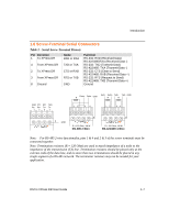
Introduction Table 4 - Front Panel Components Item 1 2 3 4 5, 6, 7 8 9 10 11 12 13 14 15 16 17 18 19 20 21 22 Component Screw terminal Screw terminal Screw terminal Screw terminal Screw terminal Screw terminal Reset switch LED (Red) LED (Green) LED (Yellow) LED (Green) Connector (RJ45) Connector (RJ45) LED (Yellow) LED (Yellow) Switch Screw terminal Screw terminal Screw terminal Screw terminal Name RXD or RXA CTS or RXB RTS or TXB TXD or TXA NC GND RESET Fault or Configuration Ready Activity Link Ethernet port Serial port Serial TXD Serial RXD Switch for screw block DC + (or AC) Ground DC - (or AC) Ground Purpose RS-232: RXD (Received Data) RS-422/485:RXA (Received Data -) RS-232: CTS (Clear to Send) RS-422/485: RXB (Received Data +) RS-232: RTS (Request to Send) RS-422/485: TXB (Transmit Data +) RS-232: TXD (Transmit Data) RS-422/485: TXA (Transmit Data -) No connection Signal ground Push to power reset and initialize SOLID: Fault in XPress DR communication (read error) or XPress DR is in Configuration Mode SOLID: Ready, Flashing: Error Message FLASHING: Network traffic SOLID: XPress DR has good Ethernet link RJ45 connector for Ethernet 10BaseT RJ45 connector for RS-232,RS-422/485 FLASHING: Indicates transmission from the serial port FLASHING: Indicates reception to the serial port UP: Serial RS-232 DOWN: Serial RS-422/485 Operating power, DC positive or AC Earth ground Operating power, DC negative or AC Earth ground Note: For RS-485 2-wire functionality, pins 1 & 4 and 2 & 3 of the screw terminals must be connected together. 1-12 DSTni-XPress DR User Guide
-
 1
1 -
2
-
3
-
4
-
5
-
6
-
7
-
8
-
9
-
10
-
11
-
12
-
13
-
14
-
15
-
16
-
17
-
18
-
19
-
20
-
 21
21 -
 22
22 -
 23
23 -
 24
24 -
 25
25 -
 26
26 -
 27
27 -
 28
28 -
 29
29 -
 30
30 -
 31
31 -
32
-
33
-
34
-
35
-
36
-
37
-
38
-
39
-
40
-
41
-
42
-
43
-
44
-
45
-
46
-
47
-
48
-
49
-
50
-
51
-
52
-
53
-
54
-
55
-
56
-
57
-
58
-
59
-
60
-
61
-
62
-
63
-
64
-
65
-
66
-
67
-
68
-
69
-
70
-
71
-
72
-
73
-
74
-
75
-
76
-
77
-
78
-
79
-
80
-
81
-
82
-
83
-
84
-
85
-
86
-
87
-
88
-
89
-
90
-
91
-
92
-
93
-
94
-
95
-
96
-
97
-
98
-
99
-
100
-
101
-
102
-
103
-
104
-
105
-
106
-
107
-
108
-
109
-
110
-
111
-
112
-
113
-
114
-
115
-
116
-
117
-
118
-
119
-
120
-
121
-
122
-
123
-
124
-
125
-
126
-
127
-
128
-
129
-
130
-
131
-
132
-
133
-
134
-
135
-
136
-
137
-
138
-
139
-
140
-
141
-
142
-
143
-
144
-
145
-
146
-
147
-
148
-
149
 |
 |
