Lantronix XPress-DR-IAP XPress-DR / XPress-DR-IAP - User Guide - Page 58
Server Configuration (Network Configuration), 4.2 Using the Serial Port, 5.1 IP Address
 |
View all Lantronix XPress-DR-IAP manuals
Add to My Manuals
Save this manual to your list of manuals |
Page 58 highlights
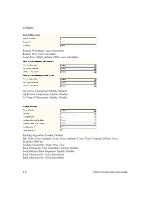
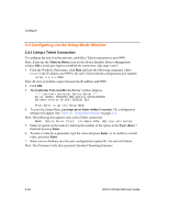
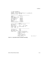
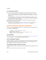
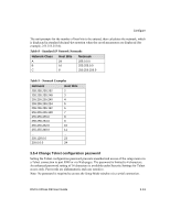
Configure 3.4.2 Using the Serial Port If you want to initially configure the unit through a serial connection, follow these steps: 1. Connect a console terminal or PC running a terminal emulation program to your unit's serial port. The default serial port settings are 9600 baud, 8 bits, no parity, 1 stop bit, no flow control. 2. To enter Setup Mode, cycle the unit's power (power off and back on). After power-up, the self-test begins and the red Diagnostic LED starts blinking. You have one second to enter three lowercase x characters (xxx). Note: The easiest way to enter Setup Mode is to hold down the x key at the terminal (or emulation) while powering up the unit. 3. At this point, the screen display is the same as when you use a Telnet connection. To continue with a serial port login, go to Using a Telnet Connection on page 3-10. 3.5 Server Configuration (Network Configuration) These are the unit's basic network parameters. The following parameters are displayed when you select Server configuration. IP Address : (000) .(000) .(000) .(000) Set Gateway IP Address (N) Netmask: Number of Bits for Host Part (0=default) Change telnet config password (N) (00) 3.5.1 IP Address The IP address must be set to a unique value in your network. See Methods of Assigning the IP Address on page 2-3 for more information about IP addressing. 3.5.2 Set Gateway IP Address The gateway address, or router, allows communication to other LAN segments. The gateway address should be the IP address of the router connected to the same LAN segment as the unit. The gateway address must be within the local network. 3.5.3 Netmask: Number of Bits for Host Part A netmask defines the number of bits taken from the IP address that are assigned for the host section. Note: Class A: 24 bits; Class B: 16 bits; Class C: 8 bits. 3-12 DSTni-XPress DR User Guide
-
 1
1 -
2
-
3
-
4
-
5
-
6
-
7
-
8
-
9
-
10
-
11
-
12
-
13
-
14
-
15
-
16
-
17
-
18
-
19
-
20
-
21
-
22
-
23
-
24
-
25
-
26
-
27
-
28
-
29
-
30
-
31
-
32
-
33
-
34
-
35
-
36
-
37
-
38
-
39
-
40
-
41
-
42
-
43
-
44
-
45
-
46
-
47
-
48
-
49
-
50
-
51
-
52
-
 53
53 -
 54
54 -
 55
55 -
 56
56 -
 57
57 -
 58
58 -
 59
59 -
 60
60 -
 61
61 -
 62
62 -
 63
63 -
64
-
65
-
66
-
67
-
68
-
69
-
70
-
71
-
72
-
73
-
74
-
75
-
76
-
77
-
78
-
79
-
80
-
81
-
82
-
83
-
84
-
85
-
86
-
87
-
88
-
89
-
90
-
91
-
92
-
93
-
94
-
95
-
96
-
97
-
98
-
99
-
100
-
101
-
102
-
103
-
104
-
105
-
106
-
107
-
108
-
109
-
110
-
111
-
112
-
113
-
114
-
115
-
116
-
117
-
118
-
119
-
120
-
121
-
122
-
123
-
124
-
125
-
126
-
127
-
128
-
129
-
130
-
131
-
132
-
133
-
134
-
135
-
136
-
137
-
138
-
139
-
140
-
141
-
142
-
143
-
144
-
145
-
146
-
147
-
148
-
149
 |
 |
