Lenovo ThinkStation D20 Hardware Maintenance Manual - Page 142
Replacing the front panel connectors assembly
 |
View all Lenovo ThinkStation D20 manuals
Add to My Manuals
Save this manual to your list of manuals |
Page 142 highlights
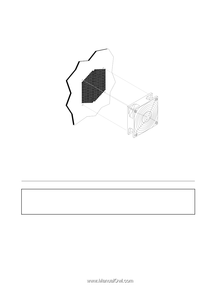
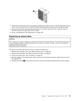
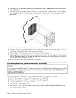
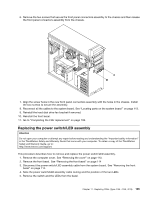
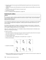
3. Disconnect the fan assembly cable from the system board. See "Locating parts on the system board " on page 113. 4. The fan assembly is attached to the chassis by four rubber mounts. Carefully remove the four rubber mounts by breaking them or cutting them with scissors and then remove the fan assembly out of the chassis. 5. Install the new fan assembly by aligning the four rubber mounts of the fan assembly with the holes on the chassis and push the rubber mounts through the holes. 6. Pull on the tips of the rubber mounts until the fan assembly is in place. 7. Depending on which fan assembly you are replacing, reconnect the fan assembly cable to the adapter card fan assembly connector or the rear fan assembly connector on the system board. See "Locating parts on the system board " on page 113. 8. Go to "Completing the FRU replacement" on page 108. Replacing the front panel connectors assembly Attention Do not open your computer or attempt any repair before reading and understanding the "Important safety information" in the ThinkStation Safety and Warranty Guide that came with your computer. To obtain a copy of the ThinkStation Safety and Warranty Guide, go to: http://www.lenovo.com/support. This section provides instructions on how to replace the front panel connectors assembly. 1. Remove the computer cover. See "Removing the cover" on page 78. 2. Remove the front bezel. See "Removing the front bezel" on page 82. 3. Locate the front panel connectors assembly. 4. Access system board components. 5. Disconnect the front audio, front USB, auxiliary LED, and IEEE 1394 cables from the system board and note the cables routing. 134 ThinkStation Hardware Maintenance Manual
-
 1
1 -
2
-
3
-
4
-
5
-
6
-
7
-
8
-
9
-
10
-
11
-
12
-
13
-
14
-
15
-
16
-
17
-
18
-
19
-
20
-
21
-
22
-
23
-
24
-
25
-
26
-
27
-
28
-
29
-
30
-
31
-
32
-
33
-
34
-
35
-
36
-
37
-
38
-
39
-
40
-
41
-
42
-
43
-
44
-
45
-
46
-
47
-
48
-
49
-
50
-
51
-
52
-
53
-
54
-
55
-
56
-
57
-
58
-
59
-
60
-
61
-
62
-
63
-
64
-
65
-
66
-
67
-
68
-
69
-
70
-
71
-
72
-
73
-
74
-
75
-
76
-
77
-
78
-
79
-
80
-
81
-
82
-
83
-
84
-
85
-
86
-
87
-
88
-
89
-
90
-
91
-
92
-
93
-
94
-
95
-
96
-
97
-
98
-
99
-
100
-
101
-
102
-
103
-
104
-
105
-
106
-
107
-
108
-
109
-
110
-
111
-
112
-
113
-
114
-
115
-
116
-
117
-
118
-
119
-
120
-
121
-
122
-
123
-
124
-
125
-
126
-
127
-
128
-
129
-
130
-
131
-
132
-
133
-
134
-
135
-
136
-
 137
137 -
 138
138 -
 139
139 -
 140
140 -
 141
141 -
 142
142 -
 143
143 -
 144
144 -
 145
145 -
 146
146 -
 147
147 -
148
-
149
-
150
-
151
-
152
-
153
-
154
-
155
-
156
-
157
-
158
-
159
-
160
-
161
-
162
-
163
-
164
-
165
-
166
-
167
-
168
-
169
-
170
-
171
-
172
-
173
-
174
-
175
-
176
-
177
-
178
-
179
-
180
-
181
-
182
-
183
-
184
-
185
-
186
-
187
-
188
-
189
-
190
-
191
-
192
-
193
-
194
-
195
-
196
-
197
-
198
-
199
-
200
-
201
-
202
-
203
-
204
-
205
-
206
-
207
-
208
-
209
-
210
-
211
-
212
-
213
-
214
-
215
-
216
-
217
-
218
-
219
-
220
-
221
-
222
-
223
-
224
-
225
-
226
-
227
-
228
-
229
-
230
-
231
-
232
-
233
-
234
-
235
-
236
-
237
-
238
-
239
-
240
-
241
-
242
-
243
-
244
-
245
-
246
-
247
-
248
-
249
-
250
-
251
-
252
-
253
-
254
-
255
-
256
-
257
-
258
-
259
-
260
-
261
-
262
-
263
-
264
-
265
-
266
-
267
-
268
-
269
-
270
 |
 |