Lenovo ThinkStation D20 Hardware Maintenance Manual - Page 143
Replacing the power switch/LED assembly
 |
View all Lenovo ThinkStation D20 manuals
Add to My Manuals
Save this manual to your list of manuals |
Page 143 highlights
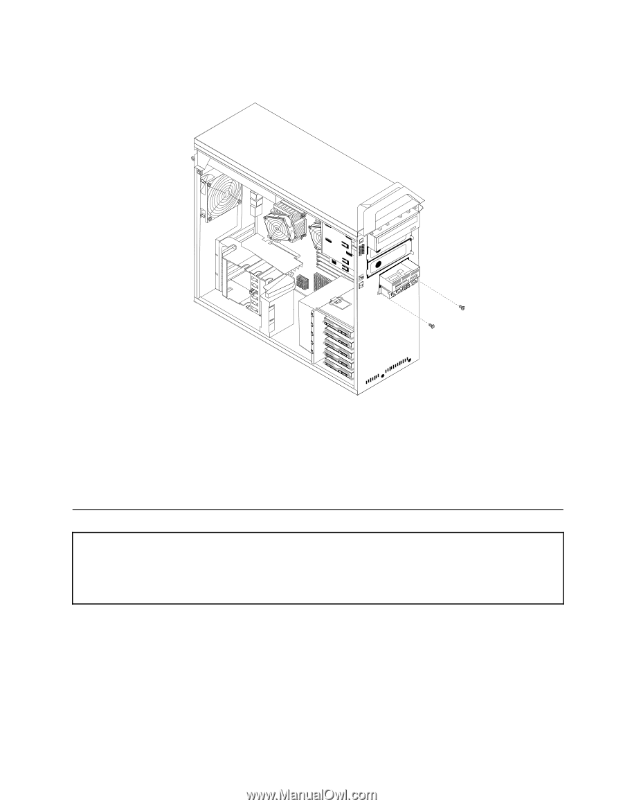
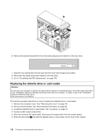
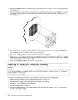
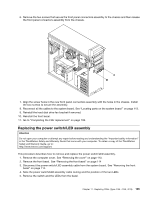
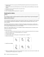
6. Remove the two screws that secure the front panel connectors assembly to the chassis and then release the front panel connectors assembly from the chassis. 7. Align the screw holes in the new front panel connectors assembly with the holes in the chassis. Install the two screws to secure the assembly. 8. Reconnect all the cables to the system board. See "Locating parts on the system board " on page 113. 9. Reinstall the hard disk drive fan bracket if removed. 10. Reinstall the front bezel. 11. Go to "Completing the FRU replacement" on page 108. Replacing the power switch/LED assembly Attention Do not open your computer or attempt any repair before reading and understanding the "Important safety information" in the ThinkStation Safety and Warranty Guide that came with your computer. To obtain a copy of the ThinkStation Safety and Warranty Guide, go to: http://www.lenovo.com/support. This procedure describes how to remove and replace the power switch/LED assembly. 1. Remove the computer cover. See "Removing the cover" on page 110. 2. Remove the front bezel. See "Removing the front bezel" on page 114 3. Disconnect the power switch/LED assembly cable from the system board. See "Removing the front bezel" on page 114. 4. Note the power switch/LED assembly cable routing and the position of the two LEDs. 5. Remove the switch and the LEDs from the bezel. Chapter 11. Replacing FRUs (Type 4155, 4158, 4218) 135
-
 1
1 -
2
-
3
-
4
-
5
-
6
-
7
-
8
-
9
-
10
-
11
-
12
-
13
-
14
-
15
-
16
-
17
-
18
-
19
-
20
-
21
-
22
-
23
-
24
-
25
-
26
-
27
-
28
-
29
-
30
-
31
-
32
-
33
-
34
-
35
-
36
-
37
-
38
-
39
-
40
-
41
-
42
-
43
-
44
-
45
-
46
-
47
-
48
-
49
-
50
-
51
-
52
-
53
-
54
-
55
-
56
-
57
-
58
-
59
-
60
-
61
-
62
-
63
-
64
-
65
-
66
-
67
-
68
-
69
-
70
-
71
-
72
-
73
-
74
-
75
-
76
-
77
-
78
-
79
-
80
-
81
-
82
-
83
-
84
-
85
-
86
-
87
-
88
-
89
-
90
-
91
-
92
-
93
-
94
-
95
-
96
-
97
-
98
-
99
-
100
-
101
-
102
-
103
-
104
-
105
-
106
-
107
-
108
-
109
-
110
-
111
-
112
-
113
-
114
-
115
-
116
-
117
-
118
-
119
-
120
-
121
-
122
-
123
-
124
-
125
-
126
-
127
-
128
-
129
-
130
-
131
-
132
-
133
-
134
-
135
-
136
-
137
-
 138
138 -
 139
139 -
 140
140 -
 141
141 -
 142
142 -
 143
143 -
 144
144 -
 145
145 -
 146
146 -
 147
147 -
 148
148 -
149
-
150
-
151
-
152
-
153
-
154
-
155
-
156
-
157
-
158
-
159
-
160
-
161
-
162
-
163
-
164
-
165
-
166
-
167
-
168
-
169
-
170
-
171
-
172
-
173
-
174
-
175
-
176
-
177
-
178
-
179
-
180
-
181
-
182
-
183
-
184
-
185
-
186
-
187
-
188
-
189
-
190
-
191
-
192
-
193
-
194
-
195
-
196
-
197
-
198
-
199
-
200
-
201
-
202
-
203
-
204
-
205
-
206
-
207
-
208
-
209
-
210
-
211
-
212
-
213
-
214
-
215
-
216
-
217
-
218
-
219
-
220
-
221
-
222
-
223
-
224
-
225
-
226
-
227
-
228
-
229
-
230
-
231
-
232
-
233
-
234
-
235
-
236
-
237
-
238
-
239
-
240
-
241
-
242
-
243
-
244
-
245
-
246
-
247
-
248
-
249
-
250
-
251
-
252
-
253
-
254
-
255
-
256
-
257
-
258
-
259
-
260
-
261
-
262
-
263
-
264
-
265
-
266
-
267
-
268
-
269
-
270
 |
 |