Lenovo ThinkStation D20 Hardware Maintenance Manual - Page 92
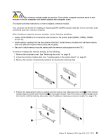
Replacing a memory module
 |
View all Lenovo ThinkStation D20 manuals
Add to My Manuals
Save this manual to your list of manuals |
Page 92 highlights
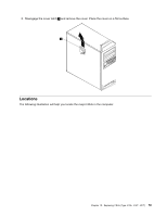
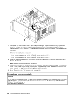
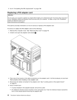
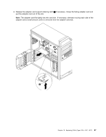
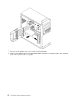
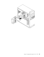
7. Ensure that the new power supply is the correct replacement. Some power supplies automatically sense the voltage, some power supplies are voltage specific, and some power supplies have a voltage-selection switch. If there is a voltage-selection switch, use a ballpoint pen to slide the switch, if necessary. Note: For models that have a switch: • If the voltage supply range is 100-127 V AC, set the switch to 115 V. • If the voltage supply range is 200-240 V AC, set the switch to 230 V. 8. Install the new power supply into the chassis so that the screw holes in the power supply align with those in the chassis. Note: Use only the screws provided by Lenovo. 9. Install and tighten the five screws at the rear of the chassis to secure the power supply. Reconnect all power supply cables to the drives, adapter cards, and the system board. Make sure to reconnect the power cable to the graphics cards that require an additional cable. 10. Go to "Completing the FRU replacement" on page 108. Replacing a memory module Attention Do not open your computer or attempt any repair before reading and understanding the "Important safety information" in the ThinkStation Safety and Warranty Guide that came with your computer. To obtain a copy of the ThinkStation Safety and Warranty Guide, go to: http://www.lenovo.com/support. 84 ThinkStation Hardware Maintenance Manual
-
 1
1 -
2
-
3
-
4
-
5
-
6
-
7
-
8
-
9
-
10
-
11
-
12
-
13
-
14
-
15
-
16
-
17
-
18
-
19
-
20
-
21
-
22
-
23
-
24
-
25
-
26
-
27
-
28
-
29
-
30
-
31
-
32
-
33
-
34
-
35
-
36
-
37
-
38
-
39
-
40
-
41
-
42
-
43
-
44
-
45
-
46
-
47
-
48
-
49
-
50
-
51
-
52
-
53
-
54
-
55
-
56
-
57
-
58
-
59
-
60
-
61
-
62
-
63
-
64
-
65
-
66
-
67
-
68
-
69
-
70
-
71
-
72
-
73
-
74
-
75
-
76
-
77
-
78
-
79
-
80
-
81
-
82
-
83
-
84
-
85
-
86
-
 87
87 -
 88
88 -
 89
89 -
 90
90 -
 91
91 -
 92
92 -
 93
93 -
 94
94 -
 95
95 -
 96
96 -
 97
97 -
98
-
99
-
100
-
101
-
102
-
103
-
104
-
105
-
106
-
107
-
108
-
109
-
110
-
111
-
112
-
113
-
114
-
115
-
116
-
117
-
118
-
119
-
120
-
121
-
122
-
123
-
124
-
125
-
126
-
127
-
128
-
129
-
130
-
131
-
132
-
133
-
134
-
135
-
136
-
137
-
138
-
139
-
140
-
141
-
142
-
143
-
144
-
145
-
146
-
147
-
148
-
149
-
150
-
151
-
152
-
153
-
154
-
155
-
156
-
157
-
158
-
159
-
160
-
161
-
162
-
163
-
164
-
165
-
166
-
167
-
168
-
169
-
170
-
171
-
172
-
173
-
174
-
175
-
176
-
177
-
178
-
179
-
180
-
181
-
182
-
183
-
184
-
185
-
186
-
187
-
188
-
189
-
190
-
191
-
192
-
193
-
194
-
195
-
196
-
197
-
198
-
199
-
200
-
201
-
202
-
203
-
204
-
205
-
206
-
207
-
208
-
209
-
210
-
211
-
212
-
213
-
214
-
215
-
216
-
217
-
218
-
219
-
220
-
221
-
222
-
223
-
224
-
225
-
226
-
227
-
228
-
229
-
230
-
231
-
232
-
233
-
234
-
235
-
236
-
237
-
238
-
239
-
240
-
241
-
242
-
243
-
244
-
245
-
246
-
247
-
248
-
249
-
250
-
251
-
252
-
253
-
254
-
255
-
256
-
257
-
258
-
259
-
260
-
261
-
262
-
263
-
264
-
265
-
266
-
267
-
268
-
269
-
270
 |
 |
