Maytag MED5800TW Technical Education - Page 28
Vent system chart, Determine vent path, Determine vent length and elbows needed, for best drying
 |
View all Maytag MED5800TW manuals
Add to My Manuals
Save this manual to your list of manuals |
Page 28 highlights
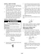
Determine vent path • Select the route that will provide the straightest and most direct path outdoors. • Plan the installation to use the fewest number of elbows and turns. • When using elbows or making turns, allow as much room as possible. • Bend vent gradually to avoid kinking. • Use the fewest 90° turns possible. Determine vent length and elbows needed for best drying performance • Use the following Vent system chart to determine type of vent material and hood combinations acceptable to use. NOTE: Do not use vent runs longer than those specified in the Vent system chart. Exhaust systems longer than those specified will: • Shorten the life of the dryer. • Reduce performance, resulting in longer drying times and increased energy usage. The Vent system chart provides venting requirements that will help to achieve the best drying performance. Vent system chart Number of 90º turns or elbows 0 1 2 3 4 Type of vent Box or Louvered hoods Angled hoods Rigid metal 64 ft (20 m) Flexible metal 36 ft (11 m) 58 ft (17.7 m) 28 ft (8.5 m) Rigid metal 54 ft (16.5 m) 48 ft (14.6 m) Flexible metal 31 ft (9.4 m) 23 ft (7 m) Rigid metal 44 ft (13.4 m) 38 ft (11.6 m) Flexible metal 27 ft (8.2 m) 19 ft (5.8 m) Rigid metal 35 ft (10.7 m) 29 ft (8.8 m) Flexible metal 25 ft (7.6 m) 17 ft (5.2 m) Rigid metal 27 ft (8.2 m) 21 ft (6.4 m) Flexible metal 23 ft (7 m) 15 ft (4.6 m) 2-20
-
 1
1 -
2
-
3
-
4
-
5
-
6
-
7
-
8
-
9
-
10
-
11
-
12
-
13
-
14
-
15
-
16
-
17
-
18
-
19
-
20
-
21
-
22
-
 23
23 -
 24
24 -
 25
25 -
 26
26 -
 27
27 -
 28
28 -
 29
29 -
 30
30 -
 31
31 -
 32
32 -
 33
33 -
34
-
35
-
36
-
37
-
38
-
39
-
40
-
41
-
42
-
43
-
44
-
45
-
46
-
47
-
48
-
49
-
50
-
51
-
52
-
53
-
54
-
55
-
56
-
57
-
58
-
59
-
60
-
61
-
62
-
63
-
64
-
65
-
66
-
67
-
68
-
69
-
70
-
71
-
72
-
73
-
74
-
75
-
76
-
77
-
78
-
79
-
80
-
81
-
82
-
83
-
84
-
85
-
86
-
87
-
88
 |
 |
