Maytag MED5800TW Technical Education - Page 67
Diagnostics & Troubleshooting
 |
View all Maytag MED5800TW manuals
Add to My Manuals
Save this manual to your list of manuals |
Page 67 highlights
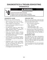
DIAGNOSTICS & TROUBLESHOOTING DIAGNOSTICS WARNING Electrical Shock Hazard Disconnect power before servicing. Replace all parts and panels before operating. Failure to do so can result in death or electrical shock. DIAGNOSTIC GUIDE Before servicing, check the following: • Make sure there is power at the wall outlet. • Has a household fuse blown or circuit breaker tripped? Time delay fuse? • Is dryer vent properly installed and clear of lint or obstructions? • All tests/checks should be made with a VOM (volt-ohm-milliammeter) or DVM (digital-voltmeter) having a sensitivity of 20,000 Ω per volt DC or greater. • Check all connections before replacing components. Look for broken or loose wires, failed terminals, or wires not pressed into connectors far enough. • A potential cause of a control not functioning is corrosion on connections. Observe connections and check for continuity with an ohmmeter. • Connectors: Look at top of connector. Check for broken or loose wires. Check for wires not pressed into connector far enough to engage metal barbs. • Resistance checks must be made with dryer unplugged or power disconnected. LESS DRY TEST Begin with a fully assembled, empty dryer with clean lint screen. Be sure dryer is connected to a known good power source. 1. Set the following configuration: • Door - must be closed • Timer - Less Dry • Temperature switch - High • End of Cycle Signal switch - Louder 2. Press the Push to Start (PTS) switch. After approximately 16 seconds, the Timer will start to advance to the Off position. If this function does not occur, proceed to the Diagnostic Test. DIAGNOSTIC TEST This diagnostic test allows factory/service personnel to test and verify all inputs to the electronic control. The basic operation of this test is to notify the operator with an audible beep every time the status of an input to the control changes state. This test is performed with a fully assembled dryer, connected to a known good power source. 6-1
-
 1
1 -
2
-
3
-
4
-
5
-
6
-
7
-
8
-
9
-
10
-
11
-
12
-
13
-
14
-
15
-
16
-
17
-
18
-
19
-
20
-
21
-
22
-
23
-
24
-
25
-
26
-
27
-
28
-
29
-
30
-
31
-
32
-
33
-
34
-
35
-
36
-
37
-
38
-
39
-
40
-
41
-
42
-
43
-
44
-
45
-
46
-
47
-
48
-
49
-
50
-
51
-
52
-
53
-
54
-
55
-
56
-
57
-
58
-
59
-
60
-
61
-
 62
62 -
 63
63 -
 64
64 -
 65
65 -
 66
66 -
 67
67 -
 68
68 -
 69
69 -
 70
70 -
 71
71 -
 72
72 -
73
-
74
-
75
-
76
-
77
-
78
-
79
-
80
-
81
-
82
-
83
-
84
-
85
-
86
-
87
-
88
 |
 |
