Maytag MED5800TW Technical Education - Page 71
Door Switch Test, Temperature Switch Test, Wrinkle Prevent Switch On/Off Test, End of Cycle Signal
 |
View all Maytag MED5800TW manuals
Add to My Manuals
Save this manual to your list of manuals |
Page 71 highlights
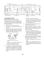
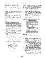
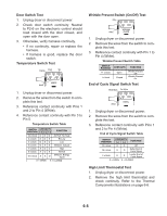
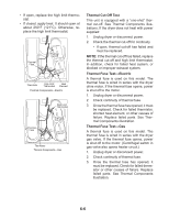
Door Switch Test 1. Unplug dryer or disconnect power. 2. Check door switch continuity. Neutral to P2-6 on the electronic control should read closed with the door closed, and open with the door open. 3. Otherwise, verify harness continuity. • If no continuity, repair or replace the harness. • If harness is good, replace the door switch. Temperature Switch Test Orange Violet Tan 1 23 4 5 White FABRIC 1. Unplug dryer or disconnect power. 2. Remove the wires from the switch to complete this test. 3. Reference contact continuity with Pins 1 and 2 to Pin 4 (White). 4. Reference contact continuity with Pin 3 to Pin 5. Temperature Switch Table SWITCH CONTACTS POSITION 3-5 2-4 1-4 FUNCTION 12 o'clock O O O Air Fluff, No Heat 2 o'clock O O X Ex-Low 4 o'clock O X O Low 5 o'clock O X X Medium, Casual 7 o'clock X O O High 8 o'clock X O X Normal 10 o'clock X X O Medium, Energy Saver O = OPEN X = CLOSED Wrinkle Prevent Switch (On/Off) Test Gray White 1 4 WRINKLE GUARD 1. Unplug dryer or disconnect power. 2. Remove the wires from the switch to complete this test. 3. Reference contact continuity with Pin 1 to Pin 4 (White). Wrinkle Prevent Switch Table SWITCH POSITION 11 o'clock 1 o'clock CONTACTS Open Closed FUNCTION Wrinkle Prevent Off Wrinkle Prevent On End of Cycle Signal Switch Test White-Black Tan-White White 12 4 SIGNAL 1. Unplug dryer or disconnect power. 2. Remove the wires from the switch to complete this test. 3. Reference contact continuity with Pins 1 and 2 to Pin 4 (White). End of Cycle Signal Switch Table SWITCH POSITION CONTACTS 1-4 2-4 FUNCTION 10 o'clock O O Off 12 o'clock X O Softer End of Cycle Signal 2 o'clock O X Louder End of Cycle Signal O = OPEN X = CLOSED High Limit Thermostat Test 1. Unplug dryer or disconnect power. 2. Remove the high limit thermostat and check continuity. Refer to the Thermal Components illustrations on page 6-6. 6-5
-
 1
1 -
2
-
3
-
4
-
5
-
6
-
7
-
8
-
9
-
10
-
11
-
12
-
13
-
14
-
15
-
16
-
17
-
18
-
19
-
20
-
21
-
22
-
23
-
24
-
25
-
26
-
27
-
28
-
29
-
30
-
31
-
32
-
33
-
34
-
35
-
36
-
37
-
38
-
39
-
40
-
41
-
42
-
43
-
44
-
45
-
46
-
47
-
48
-
49
-
50
-
51
-
52
-
53
-
54
-
55
-
56
-
57
-
58
-
59
-
60
-
61
-
62
-
63
-
64
-
65
-
 66
66 -
 67
67 -
 68
68 -
 69
69 -
 70
70 -
 71
71 -
 72
72 -
 73
73 -
 74
74 -
 75
75 -
 76
76 -
77
-
78
-
79
-
80
-
81
-
82
-
83
-
84
-
85
-
86
-
87
-
88
 |
 |
