Maytag MED5800TW Technical Education - Page 66
Drive Motor
 |
View all Maytag MED5800TW manuals
Add to My Manuals
Save this manual to your list of manuals |
Page 66 highlights
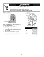
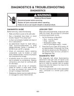
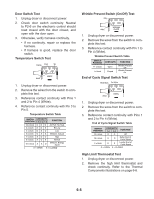
WARNING Electrical Shock Hazard Disconnect power before servicing. Replace all parts and panels before operating. Failure to do so can result in death or electrical shock. DRIVE MOTOR Main Winding: Blue Wire (In Back and Bare) Copper Wire (Pin 5) Connector Refer to page 4-10 for the procedure for accessing the drive motor. 1. Unplug dryer or disconnect power. 2. Turn off gas supply to dryer. 3. Disconnect the wire connector from the mo- tor terminals. 4. Set the ohmmeter to the R x 1 scale. 5. Measure the drive motor main and start windings, as shown in the chart. Start Winding: Blue Wire (In Back and Bare) Copper Wire (Pin 3) WINDING RESISTANCE CONTACT POINTS Ω OF MEASUREMENT MAIN 1.4 - 2.6 Blue wire in back at pin 4 and bare copper wire on pin 5 of black drive motor switch START 1.4 - 2.8 Blue wire in back at pin 4 and bare copper wire on pin 3 of black drive motor switch 5-6
-
 1
1 -
2
-
3
-
4
-
5
-
6
-
7
-
8
-
9
-
10
-
11
-
12
-
13
-
14
-
15
-
16
-
17
-
18
-
19
-
20
-
21
-
22
-
23
-
24
-
25
-
26
-
27
-
28
-
29
-
30
-
31
-
32
-
33
-
34
-
35
-
36
-
37
-
38
-
39
-
40
-
41
-
42
-
43
-
44
-
45
-
46
-
47
-
48
-
49
-
50
-
51
-
52
-
53
-
54
-
55
-
56
-
57
-
58
-
59
-
60
-
 61
61 -
 62
62 -
 63
63 -
 64
64 -
 65
65 -
 66
66 -
 67
67 -
 68
68 -
 69
69 -
 70
70 -
 71
71 -
72
-
73
-
74
-
75
-
76
-
77
-
78
-
79
-
80
-
81
-
82
-
83
-
84
-
85
-
86
-
87
-
88
 |
 |
