Maytag MED5800TW Technical Education - Page 56
Removing The Flame Sensor And, Gas Burner Assembly Gas Models Only
 |
View all Maytag MED5800TW manuals
Add to My Manuals
Save this manual to your list of manuals |
Page 56 highlights
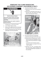
REMOVING THE FLAME SENSOR AND GAS BURNER ASSEMBLY (GAS MODELS ONLY) WARNING 5. To remove the flame sensor: a) Remove the two wires from the sensor terminals. b) Remove the hex-head screw, then unhook the tab, and remove the flame sensor from the burner venturi. Electrical Shock Hazard Disconnect power before servicing. Replace all parts and panels before operating. Failure to do so can result in death or electrical shock. Flame Sensor Screw BU & WH Wires) Burner Venturi 1. Unplug dryer or disconnect power. Tab 2. Turn off gas supply to dryer. 3. Remove the cabinet front from the dryer (see pages 4-5 & 4-6 for the procedure). 4. Remove the belt and drum from the dryer (see page 4-8 for the procedure). Burner Assembly 6. To remove the burner assembly: a) Disconnect the gas line from the dryer. b) Disconnect the following wire connectors from the burner assembly components (see the top left photo on page 4-17): • Connector from the flame sensor. • Burner harness connector from the main harness. c) Remove the 5/16˝ hex-head screw from the burner support bracket and remove the bracket from the bottom of the assembly. 4-16
-
 1
1 -
2
-
3
-
4
-
5
-
6
-
7
-
8
-
9
-
10
-
11
-
12
-
13
-
14
-
15
-
16
-
17
-
18
-
19
-
20
-
21
-
22
-
23
-
24
-
25
-
26
-
27
-
28
-
29
-
30
-
31
-
32
-
33
-
34
-
35
-
36
-
37
-
38
-
39
-
40
-
41
-
42
-
43
-
44
-
45
-
46
-
47
-
48
-
49
-
50
-
 51
51 -
 52
52 -
 53
53 -
 54
54 -
 55
55 -
 56
56 -
 57
57 -
 58
58 -
 59
59 -
 60
60 -
 61
61 -
62
-
63
-
64
-
65
-
66
-
67
-
68
-
69
-
70
-
71
-
72
-
73
-
74
-
75
-
76
-
77
-
78
-
79
-
80
-
81
-
82
-
83
-
84
-
85
-
86
-
87
-
88
 |
 |
