Maytag MED5800TW Technical Education - Page 63
Flame Sensor, Gas Burner Coils
 |
View all Maytag MED5800TW manuals
Add to My Manuals
Save this manual to your list of manuals |
Page 63 highlights
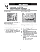
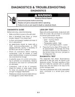
WARNING Electrical Shock Hazard Disconnect power before servicing. Replace all parts and panels before operating. Failure to do so can result in death or electrical shock. FLAME SENSOR GAS BURNER COILS Burner Coils Refer to page 4-16 for the procedure for accessing the flame sensor. 1. Unplug dryer or disconnect power. 2. Turn off gas supply to dryer. 3. Disconnect the wire connectors from the flame sensor terminals. 4. Set the ohmmeter to the R x 1 scale. 5. Touch the ohmmeter test leads to the flame sensor terminals. The meter should indicate a closed circuit (0 Ω). 4 5 1 2 3 Refer to page 4-16 for the procedure for accessing the gas burner assembly. 1. Unplug dryer or disconnect power. 2. Turn off gas supply to dryer. 3. Disconnect the wire connectors from the coil terminals. 4. Set the ohmmeter to the R x 100 scale. 5. Touch the ohmmeter test leads to pins 4 and 5 of the 2-terminal coil. The meter should indicate between 1000 and 1300 Ω. 6. Touch the ohmmeter test leads to the 3-terminal coil. The meter should indicate as follows: Pins 1 & 2 = 1300 to 1400 Ω Pins 1 & 3 = 500 to 600 Ω 5-3
-
 1
1 -
2
-
3
-
4
-
5
-
6
-
7
-
8
-
9
-
10
-
11
-
12
-
13
-
14
-
15
-
16
-
17
-
18
-
19
-
20
-
21
-
22
-
23
-
24
-
25
-
26
-
27
-
28
-
29
-
30
-
31
-
32
-
33
-
34
-
35
-
36
-
37
-
38
-
39
-
40
-
41
-
42
-
43
-
44
-
45
-
46
-
47
-
48
-
49
-
50
-
51
-
52
-
53
-
54
-
55
-
56
-
57
-
 58
58 -
 59
59 -
 60
60 -
 61
61 -
 62
62 -
 63
63 -
 64
64 -
 65
65 -
 66
66 -
 67
67 -
 68
68 -
69
-
70
-
71
-
72
-
73
-
74
-
75
-
76
-
77
-
78
-
79
-
80
-
81
-
82
-
83
-
84
-
85
-
86
-
87
-
88
 |
 |
