Motorola 49901 Instruction Manual - Page 54
Dual E&M Daughtercard Connector, Dual E&M, RemoteVU Video
 |
UPC - 786523499018
View all Motorola 49901 manuals
Add to My Manuals
Save this manual to your list of manuals |
Page 54 highlights
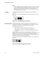
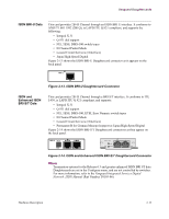
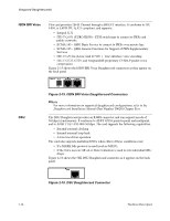
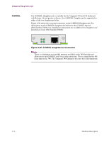
Vanguard Daughtercards Dual E&M Note The FE1 Daughtercard comes with a label "!" which means that the user should refer to the Vanguard Daughtercard Installation Guide. The purpose is to point out that the E1 interface complies with the Australian requirements ACA TS-016-1997 for connection to E1 SELV services. The E1 interface meets the IEC 60950 specifications for TNV1. The Dual E&M Daughtercard has two E&M interfaces. The ports use RJ11 connectors. Figure 2-11 shows the Dual E&M Daughtercard connectors as they appear on the back panel. Figure 2-11. Dual E&M Daughtercard Connector RemoteVU (Video) The RemoteVU Daughtercard provides complete end-to-end solution for the transport of video images over low bandwidths (as low as 2.4 kbps). It is ideal for applications such as security surveillance and remote monitoring. The daughtercard has three ports: • RJ-45 connector: for camera controls (such as pan-tilt-zoom). • BNC connector: the primary video input from a single camera. • 8 Pin Mini-DIN: connects to a custom cable that terminates in three BNC connectors. When its video ports are connected to a video multiplexor, the RemoteVU Daughtercard can support up to 64 cameras. The daughtercard converts analog video to digital, scales size, and compresses and transports the data. In addition to supporting live video streams, the daughtercard has a one-minute history buffer for capturing video before the connection is established. Figure 2-12 shows the RemoteVU Daughtercard connectors as they appear on the back panel. \ VIDEO 2 VIDEO 1 CAMERA Figure 2-12. RemoteVU Daughtercard Connector 2-12 Hardware Description
-
 1
1 -
2
-
3
-
4
-
5
-
6
-
7
-
8
-
9
-
10
-
11
-
12
-
13
-
14
-
15
-
16
-
17
-
18
-
19
-
20
-
21
-
22
-
23
-
24
-
25
-
26
-
27
-
28
-
29
-
30
-
31
-
32
-
33
-
34
-
35
-
36
-
37
-
38
-
39
-
40
-
41
-
42
-
43
-
44
-
45
-
46
-
47
-
48
-
 49
49 -
 50
50 -
 51
51 -
 52
52 -
 53
53 -
 54
54 -
 55
55 -
 56
56 -
 57
57 -
 58
58 -
 59
59 -
60
-
61
-
62
-
63
-
64
-
65
-
66
-
67
-
68
-
69
-
70
-
71
-
72
-
73
-
74
-
75
-
76
-
77
-
78
-
79
-
80
-
81
-
82
-
83
-
84
-
85
-
86
-
87
-
88
-
89
-
90
-
91
-
92
-
93
-
94
-
95
-
96
-
97
-
98
-
99
-
100
-
101
-
102
-
103
-
104
-
105
-
106
-
107
-
108
-
109
-
110
-
111
-
112
-
113
-
114
-
115
-
116
-
117
-
118
-
119
-
120
-
121
 |
 |
