Motorola 49901 Instruction Manual - Page 74
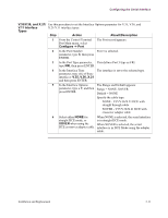
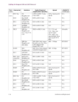
Control Terminal Port (CTP), RJ45 Pinout, RJ45 Pin, Signal, Pin Connection, on DB25F
 |
UPC - 786523499018
View all Motorola 49901 manuals
Add to My Manuals
Save this manual to your list of manuals |
Page 74 highlights
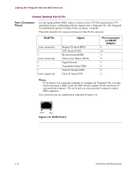
Cabling the Vanguard 340 and 340 Enhanced Control Terminal Port (CTP) Port 4 Connector Pinout Use the supplied RJ45/DB25 cable to connect to the CTP Port and perform CTP operations such as coldloading software images into a Vanguard 34x. The Vanguard 34x defaults this port to 9.6 kbps, 8 bits, no parity, 1 stop bit. This table identifies the connector pinout for this RJ-45 connector: RJ45 Pin Signal 1 (not connected) 2 3 4 (not connected) 5 6 7 8 (not connected) Request To Send (RTS) DTE Ready (DTR) Received Data (RXD) Data Carrier Detect (DCD) Signal Ground Transmitted Data (TXD) Data Set Ready (DSR) Clear To Send (CTS) Pin Connection on DB25F Adapter 4 20 3 8 7 2 6 5 Note If you plan to use a personal computer to configure the Vanguard 34x, you may need to purchase a DB25 (male) to DB9 (female) adapter for the serial port of your personal computer. The serial ports on most personal computers require DB9 connectors. The connector pins are numbered as indicated in Figure 3-4. Pin 8 Pin 1 Figure 3-4. RJ45 Pinout 3-16 Installation and Replacement
-
 1
1 -
2
-
3
-
4
-
5
-
6
-
7
-
8
-
9
-
10
-
11
-
12
-
13
-
14
-
15
-
16
-
17
-
18
-
19
-
20
-
21
-
22
-
23
-
24
-
25
-
26
-
27
-
28
-
29
-
30
-
31
-
32
-
33
-
34
-
35
-
36
-
37
-
38
-
39
-
40
-
41
-
42
-
43
-
44
-
45
-
46
-
47
-
48
-
49
-
50
-
51
-
52
-
53
-
54
-
55
-
56
-
57
-
58
-
59
-
60
-
61
-
62
-
63
-
64
-
65
-
66
-
67
-
68
-
 69
69 -
 70
70 -
 71
71 -
 72
72 -
 73
73 -
 74
74 -
 75
75 -
 76
76 -
 77
77 -
 78
78 -
 79
79 -
80
-
81
-
82
-
83
-
84
-
85
-
86
-
87
-
88
-
89
-
90
-
91
-
92
-
93
-
94
-
95
-
96
-
97
-
98
-
99
-
100
-
101
-
102
-
103
-
104
-
105
-
106
-
107
-
108
-
109
-
110
-
111
-
112
-
113
-
114
-
115
-
116
-
117
-
118
-
119
-
120
-
121
 |
 |
