Motorola 49901 Instruction Manual - Page 98
Power Up, Sequence, Detailed FT1/FE1, Power PWR LED turns
 |
UPC - 786523499018
View all Motorola 49901 manuals
Add to My Manuals
Save this manual to your list of manuals |
Page 98 highlights
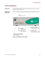
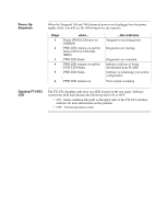
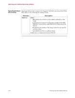
Power Up Sequence When the Vanguard 340 and 340 Enhanced power cord is plugged into the power supply outlet, you will see the following power up sequence: Stage 1 2 3 4 5 when... Power (PWR) LED turns on (GREEN) PWR LED remains on and the Status (STAT) LED blinks (RED). PWR LED blinks. PWR LED remains on and the STAT LED blinks. PWR LED blinks. 6 PWR LED remains on. ...this indicates Vanguard is receiving power. Diagnostics are starting. Diagnostics are executed. Indicates software is being downloaded from FLASH. Software is initializing your system configuration. Your system is running. Detailed FT1/FE1 LED The FT1/FE1 daughtercards have one LED located on the rear panel. Software controls the LED and indicates the following when ON or OFF: • ON - Alarm condition data path is disrupted, refer to the FT1/FE1 interface statistics for more information on the problem. • OFF - Normal operation exists.
-
 1
1 -
2
-
3
-
4
-
5
-
6
-
7
-
8
-
9
-
10
-
11
-
12
-
13
-
14
-
15
-
16
-
17
-
18
-
19
-
20
-
21
-
22
-
23
-
24
-
25
-
26
-
27
-
28
-
29
-
30
-
31
-
32
-
33
-
34
-
35
-
36
-
37
-
38
-
39
-
40
-
41
-
42
-
43
-
44
-
45
-
46
-
47
-
48
-
49
-
50
-
51
-
52
-
53
-
54
-
55
-
56
-
57
-
58
-
59
-
60
-
61
-
62
-
63
-
64
-
65
-
66
-
67
-
68
-
69
-
70
-
71
-
72
-
73
-
74
-
75
-
76
-
77
-
78
-
79
-
80
-
81
-
82
-
83
-
84
-
85
-
86
-
87
-
88
-
89
-
90
-
91
-
92
-
 93
93 -
 94
94 -
 95
95 -
 96
96 -
 97
97 -
 98
98 -
 99
99 -
 100
100 -
 101
101 -
 102
102 -
 103
103 -
104
-
105
-
106
-
107
-
108
-
109
-
110
-
111
-
112
-
113
-
114
-
115
-
116
-
117
-
118
-
119
-
120
-
121
 |
 |
