Netgear XSM4324FS Hardware Installation Guide - Page 18
Common components, Reset, One out-of-band OOB 1G Ethernet port models M4300-16X, M4300-8X8F,
 |
View all Netgear XSM4324FS manuals
Add to My Manuals
Save this manual to your list of manuals |
Page 18 highlights
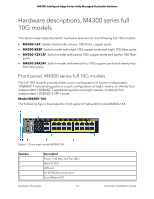
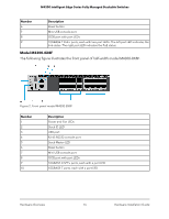
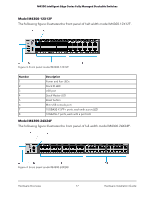
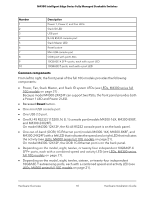
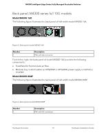
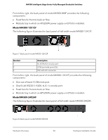
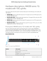
M4300 Intelligent Edge Series Fully Managed Stackable Switches Number 1 2 3 4 5 6 7 8 9 10 Description Power 1, Power 2, and Fan LEDs Stack ID LED USB port RJ-45 RS232 console port Stack Master LED Reset button Mini USB console port OOB port with port LEDs 10GBASE-X SFP+ ports, each with a port LED 10GBASE-T ports, each with a port LED Common components From left to right, the front panel of the full 10G models provides the following components: • Power, Fan, Stack Master, and Stack ID system LEDs (see LEDs, M4300 series full 10G models on page 21) . Because model M4300-24X24F can support two PSUs, the front panel provides both a Power 1 LED and Power 2 LED. • Recessed Reset button. • One mini USB console port. • One USB 2.0 port. • One RJ-45 RS232 (115200, N, 8, 1) console port (models M4300-16X, M4300-8X8F, and M4300-24X24F). On model M4300-12X12F, the RJ-45 RS232 console port is on the back panel. • One out-of-band (OOB) 1G Ethernet port (models M4300-16X, M4300-8X8F, and M4300-24X24F) with a left LED that indicates the speed and a right LED that indicates the activity (see LEDs, M4300 series full 10G models on page 21). On model M4300-12X12F, the OOB 1G Ethernet port is on the back panel. • Depending on the model, eight, twelve, or twenty-four independent 10GBASE-X SFP+ ports, each with a combined speed and activity LED (see LEDs, M4300 series full 10G models on page 21). • Depending on the model, eight, twelve, sixteen, or twenty-four independent 10GBASE-T autosensing ports, each with a combined speed and activity LED (see LEDs, M4300 series full 10G models on page 21). Hardware Overview 18 Hardware Installation Guide
-
 1
1 -
2
-
3
-
4
-
5
-
6
-
7
-
8
-
9
-
10
-
11
-
12
-
 13
13 -
 14
14 -
 15
15 -
 16
16 -
 17
17 -
 18
18 -
 19
19 -
 20
20 -
 21
21 -
 22
22 -
 23
23 -
24
-
25
-
26
-
27
-
28
-
29
-
30
-
31
-
32
-
33
-
34
-
35
-
36
-
37
-
38
-
39
-
40
-
41
-
42
-
43
-
44
-
45
-
46
-
47
-
48
-
49
-
50
-
51
-
52
-
53
-
54
-
55
-
56
-
57
-
58
-
59
-
60
-
61
-
62
-
63
-
64
-
65
-
66
-
67
-
68
-
69
 |
 |