Netgear XSM4324FS Hardware Installation Guide - Page 59
Optional Step 7: Connect a redundant power supply to model M4300-52G-POE
 |
View all Netgear XSM4324FS manuals
Add to My Manuals
Save this manual to your list of manuals |
Page 59 highlights
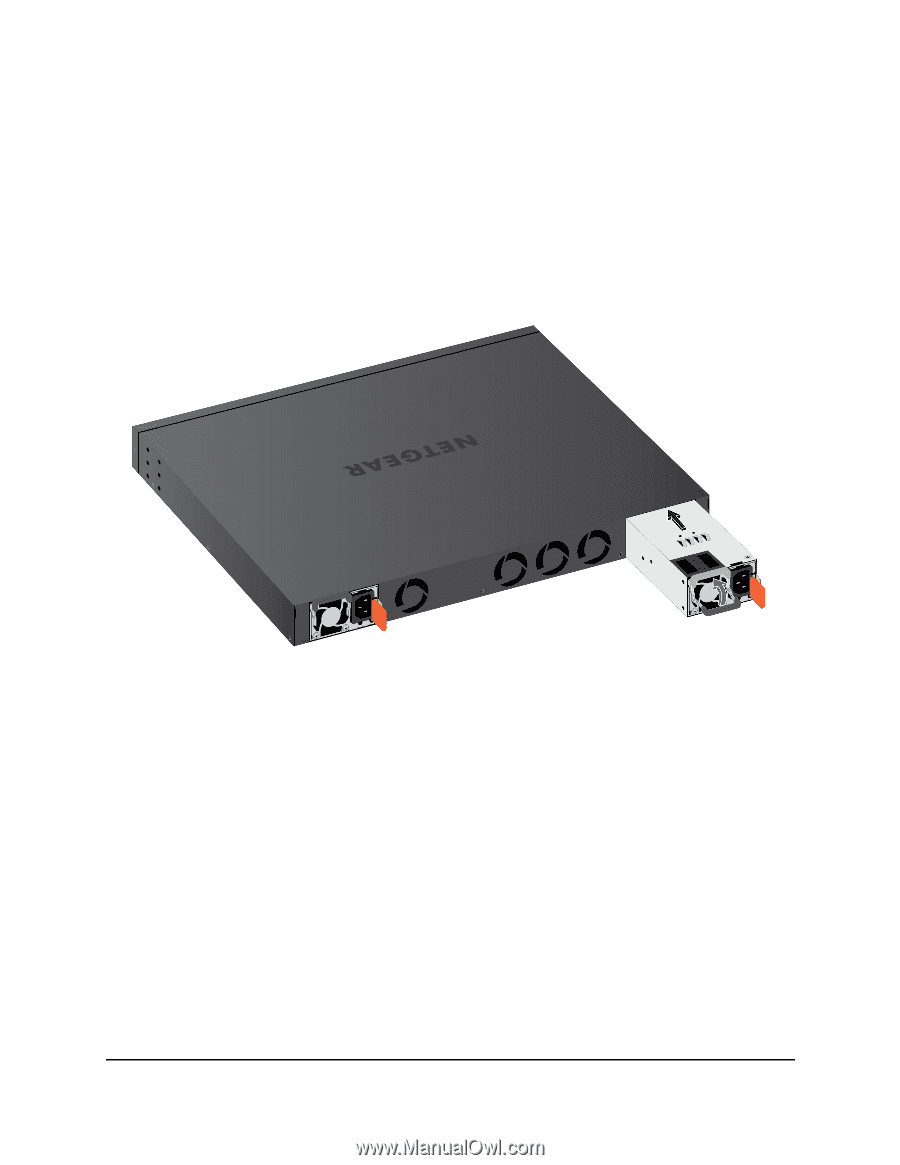
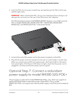
M4300 Intelligent Edge Series Fully Managed Stackable Switches 2. Insert the PSU into the power module bay, and gently push the PSU into the bay until the latch locks. WARNING: When inserting the PSU, do not use unnecessary force. Doing so can damage the connectors on the rear of the PSU and on the midplane. The following figure shows model M4300-24X24F. However, you install a second PSU in models M4300-28G, M4300-28G-POE+, M4300-48X, M4300-48XF, M4300-52G, and M4300-52G-POE+ in the same manner. 3. Connect the end of the power cord to the power receptacle on the PSU. 4. Plug the AC power cord into a power source such as a wall socket or power strip. When you install a second PSU and apply power, the Power 2 LED on the switch front panel lights. If the Power 2 LED does not light, check that the power cord is plugged in correctly and that the power source is good. Optional Step 7: Connect a redundant power supply to model M4300-52G-POE+ This procedure is optional for model M4300-52G-POE+ only, which can support an optional RPS5412 external redundant power supply (RPS). That is, model M4300-52G-POE+ can support two internal power supply units (PSUs) and an external RPS. Installation 59 Hardware Installation Guide
-
 1
1 -
2
-
3
-
4
-
5
-
6
-
7
-
8
-
9
-
10
-
11
-
12
-
13
-
14
-
15
-
16
-
17
-
18
-
19
-
20
-
21
-
22
-
23
-
24
-
25
-
26
-
27
-
28
-
29
-
30
-
31
-
32
-
33
-
34
-
35
-
36
-
37
-
38
-
39
-
40
-
41
-
42
-
43
-
44
-
45
-
46
-
47
-
48
-
49
-
50
-
51
-
52
-
53
-
 54
54 -
 55
55 -
 56
56 -
 57
57 -
 58
58 -
 59
59 -
 60
60 -
 61
61 -
 62
62 -
 63
63 -
 64
64 -
65
-
66
-
67
-
68
-
69
 |
 |