Netgear XSM4324FS Hardware Installation Guide - Page 27
Back panel, 4300 series 1G models with 10G uplinks, Models M4300-28G, M4300-28G-POE+, and M4300-52G
 |
View all Netgear XSM4324FS manuals
Add to My Manuals
Save this manual to your list of manuals |
Page 27 highlights
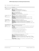
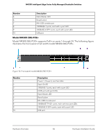
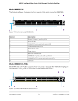
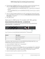
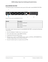
M4300 Intelligent Edge Series Fully Managed Stackable Switches • Two dedicated 10GBASE-X SFP+ ports, each with a combined speed and activity LED (see LEDs, M4300 series 1G models with 10G uplinks on page 29): - On model M4300-28 and model M4300-28G-POE+, these are port numbers 27 and 28. - On model M4300-52G and model M4300-52G-POE+, these are port numbers 51 and 52. • One out-of-band (OOB) 1G Ethernet port with a left LED that indicates the speed and a right LED that indicates the activity (see LEDs, M4300 series 1G models with 10G uplinks on page 29). • One USB 2.0 port. Back panel, 4300 series 1G models with 10G uplinks Models M4300-28G, M4300-28G-POE+, and M4300-52G The following figure illustrates the back panel of full-width models M4300-28G, M4300-28G-POE+, and M4300-52G. Figure 13. Back panel models M4300-28G, M4300-28G-POE+, and M4300-52G Number 1 2 3 Description RJ-45 RS232 console port PSU1 with AC connector Bay for PSU2 From left to right, the back panel of models M4300-28G, M4300-28G-POE+, and M4300-52G provides the following components: • One RJ-45 RS232 (115200, N, 8, 1) console port. • Fixed fans for front-to-back air flow. • Modular bay in which for model M4300-28G and model M4300-52G an APS150W power supply unit (PSU) is installed. For model M4300-28G-POE+, an APS550W PSU or APS1000W PSU is installed, depending on the product ordered. • Second modular bay for an optional second PSU. Hardware Overview 27 Hardware Installation Guide
-
 1
1 -
2
-
3
-
4
-
5
-
6
-
7
-
8
-
9
-
10
-
11
-
12
-
13
-
14
-
15
-
16
-
17
-
18
-
19
-
20
-
21
-
 22
22 -
 23
23 -
 24
24 -
 25
25 -
 26
26 -
 27
27 -
 28
28 -
 29
29 -
 30
30 -
 31
31 -
 32
32 -
33
-
34
-
35
-
36
-
37
-
38
-
39
-
40
-
41
-
42
-
43
-
44
-
45
-
46
-
47
-
48
-
49
-
50
-
51
-
52
-
53
-
54
-
55
-
56
-
57
-
58
-
59
-
60
-
61
-
62
-
63
-
64
-
65
-
66
-
67
-
68
-
69
 |
 |