Netgear XSM4324FS Hardware Installation Guide - Page 21
LEDs, M4300 series full 10G models, Second modular bay for an optional second PSU.
 |
View all Netgear XSM4324FS manuals
Add to My Manuals
Save this manual to your list of manuals |
Page 21 highlights
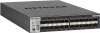
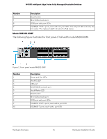
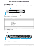
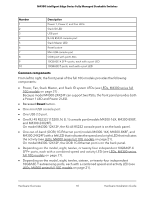
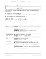
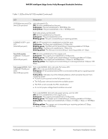
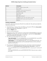
M4300 Intelligent Edge Series Fully Managed Stackable Switches Number 1 2 Description PSU1 with AC connector Bay for PSU2 From left to right, the back panel of model M4300-24X24F provides the following components: • Fixed fans for front-to-back air flow. • Modular bay in which an APS250W power supply unit (PSU) is installed. • Second modular bay for an optional second PSU. LEDs, M4300 series full 10G models The following table describes the LEDs on the front panel of the full 10G models. Table 1. LEDs of the full 10G models LED Designation Power LED Solid green. The power module is present, is supplying power to the switch, and is functioning normally. Solid yellow. The switch is booting. Blinking yellow. The system boot-up failed or another failure occurred. Off. Power is not supplied to the switch. Note: Because model M4300-24X24F can support two PSUs, the front panel provides both a Power 1 LED and Power 2 LED. PoE model (M4300-16X) PoE Max LED Off. Sufficient (more than 7W of) PoE power is available. Solid yellow. Less than 7W of PoE power is available. Blinking yellow. At least once during the previous two minutes, less than 7W of PoE power was available. Fan LED Solid green. The fans are functioning normally. Solid yellow. One or more fans failed. Off. Power is not supplied to the switch. The fans are off. Stack Master LED Solid green. The switch is functioning as a master in a stack. Off. The switch is not a member of a stack or is functioning as a slave in a stack. Stack ID LED The Stack LED contains segments that can indicate the stack unit number of the switch: Solid green indicating a number. The switch is a member of a stack. The LED displays the stack unit number. Solid green indicating E. The switch functions in ECO mode with all port LEDs turned off. Off. The switch is not a member of a stack. Hardware Overview 21 Hardware Installation Guide
-
 1
1 -
2
-
3
-
4
-
5
-
6
-
7
-
8
-
9
-
10
-
11
-
12
-
13
-
14
-
15
-
 16
16 -
 17
17 -
 18
18 -
 19
19 -
 20
20 -
 21
21 -
 22
22 -
 23
23 -
 24
24 -
 25
25 -
 26
26 -
27
-
28
-
29
-
30
-
31
-
32
-
33
-
34
-
35
-
36
-
37
-
38
-
39
-
40
-
41
-
42
-
43
-
44
-
45
-
46
-
47
-
48
-
49
-
50
-
51
-
52
-
53
-
54
-
55
-
56
-
57
-
58
-
59
-
60
-
61
-
62
-
63
-
64
-
65
-
66
-
67
-
68
-
69
 |
 |