Onkyo TX SR800 Owner Manual - Page 13
Rear panel - tx sr 800
 |
UPC - 751398004926
View all Onkyo TX SR800 manuals
Add to My Manuals
Save this manual to your list of manuals |
Page 13 highlights
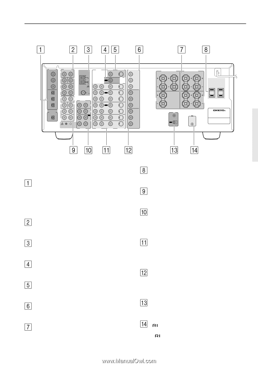
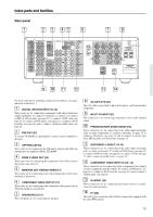
Index parts and facilities Rear panel DIGITAL INPUT COAX 1 PRE OUT R L FRONT ANTENNA AUDIO VIDEO S VIDEO MONITOR OUT 2 3 OPT 1 SUB SURR SURR BACK / R ZONE 2 FRONT 2 R SUB 3 DIGITAL OUTPUT OPT SURR R SURR BACK GND CENTER AM OUT ZONE 2 R L L FM 75 MULTI CH INPUT L AUDIO R L CENTER PHONO CD L OUT TAPE IN R L AUDIO R L AUDIO IN DVD OUT IN VIDEO 1 OUT IN VIDEO 2 IN VIDEO 3 IN VIDEO 4 VIDEO S VIDEO COMPONENT VIDEO OUTPUT Y PB PR INPUT 1 Y PB PR INPUT 2 Y PB PR CAUTION: SPEAKER IMPEDANCE 4 OHMS MIN. OR 6 OHMS MIN. / SPEAKER SEE INSTRUCTION MANUAL FOR CORRECT SETTINGS. FRONT SPEAKERS R L CENTER SPEAKER I R IN OUT SURR SPEAKERS R L AC OUTLETS AC 120V 60 Hz SWITCHED TOTAL 120W 1A MAX. SURR BACK/ ZONE 2 SPEAKERS R L REMOTE CONTROL AV RECEIVER MODEL NO. TX-SR 800 For more information regarding connection procedures, see pages indicated in brackets [ ]. DIGITAL INPUT/OUTPUT [15-19] These jacks are for connecting components with digital input and output capabilities. To connect a CD player, see page 15; to connect an MD or CD recorder, see page 15; to connect a DAT deck, see page 15; to connect a DVD player, see page 16; to connect a DVD recorder, see page 18; and to connect a digital satellite tuner, see page 19. PRE OUT [27] To use the TX-SR800 as a preamplifier, connect a power amplifier to this jack. ANTENNA [22-23] These jacks are for connecting the FM indoor antenna and AM loop antenna that are supplied with the TX-SR800. ZONE 2 VIDEO OUT [24] These jacks are for connecting the components that will be used in the remote zone (Zone 2). MONITOR OUT VIDEO/S VIDEO [17] These jacks are for connecting to the video input jacks on television monitors or projectors. COMPONENT VIDEO OUTPUT [17] These jacks are for connecting to the component video input jacks on television monitors or projectors. SPEAKERS [20-21] These terminals are for connecting the speakers. AC OUTLETS [26] This AC outlet is provided to plug in the power cord from another component. MULTI CH INPUT [27] This connector is for connecting components with a multi-channel output. PHONO/CD/TAPE AUDIO IN/OUT [15] These connectors are for connecting to the audio input and output jacks on audio components. To connect a turntable, see page 15; to connect a CD player, see page 15; and to connect a cassette tape deck, MD recorder, or CD recorder, see page 15. DVD/VIDEO1-4 IN/OUT [16-19] These connectors are for connecting to the video input and output jacks on video components. To connect a DVD player, see page 16; to connect a DVD recorder, see page 18; to connect a VCR, see page 17; and to connect a satellite tuner, see page 19. COMPONENT VIDEO INPUT1/2 [16, 18] These connectors are for connecting to the component video outputs of video components that have them. To connect a DVD player, see page 16; to connect a DVD recorder, see page 18; and to connect a satellite tuner, see page 19. IR IN/OUT [25] These connectors are for connecting the remote sensor of a multiroom kit (sold separately). [26] This jack is for connecting other Onkyo components equipped with the same terminal. 13
-
 1
1 -
2
-
3
-
4
-
5
-
6
-
7
-
 8
8 -
 9
9 -
 10
10 -
 11
11 -
 12
12 -
 13
13 -
 14
14 -
 15
15 -
 16
16 -
 17
17 -
 18
18 -
19
-
20
-
21
-
22
-
23
-
24
-
25
-
26
-
27
-
28
-
29
-
30
-
31
-
32
-
33
-
34
-
35
-
36
-
37
-
38
-
39
-
40
-
41
-
42
-
43
-
44
-
45
-
46
-
47
-
48
-
49
-
50
-
51
-
52
-
53
-
54
-
55
-
56
-
57
-
58
-
59
-
60
-
61
-
62
-
63
-
64
-
65
-
66
-
67
-
68
-
69
-
70
-
71
-
72
-
73
-
74
-
75
-
76
 |
 |