Onkyo TX SR800 Owner Manual - Page 14
and speaker cables. Doing so may adversely affect
 |
UPC - 751398004926
View all Onkyo TX SR800 manuals
Add to My Manuals
Save this manual to your list of manuals |
Page 14 highlights
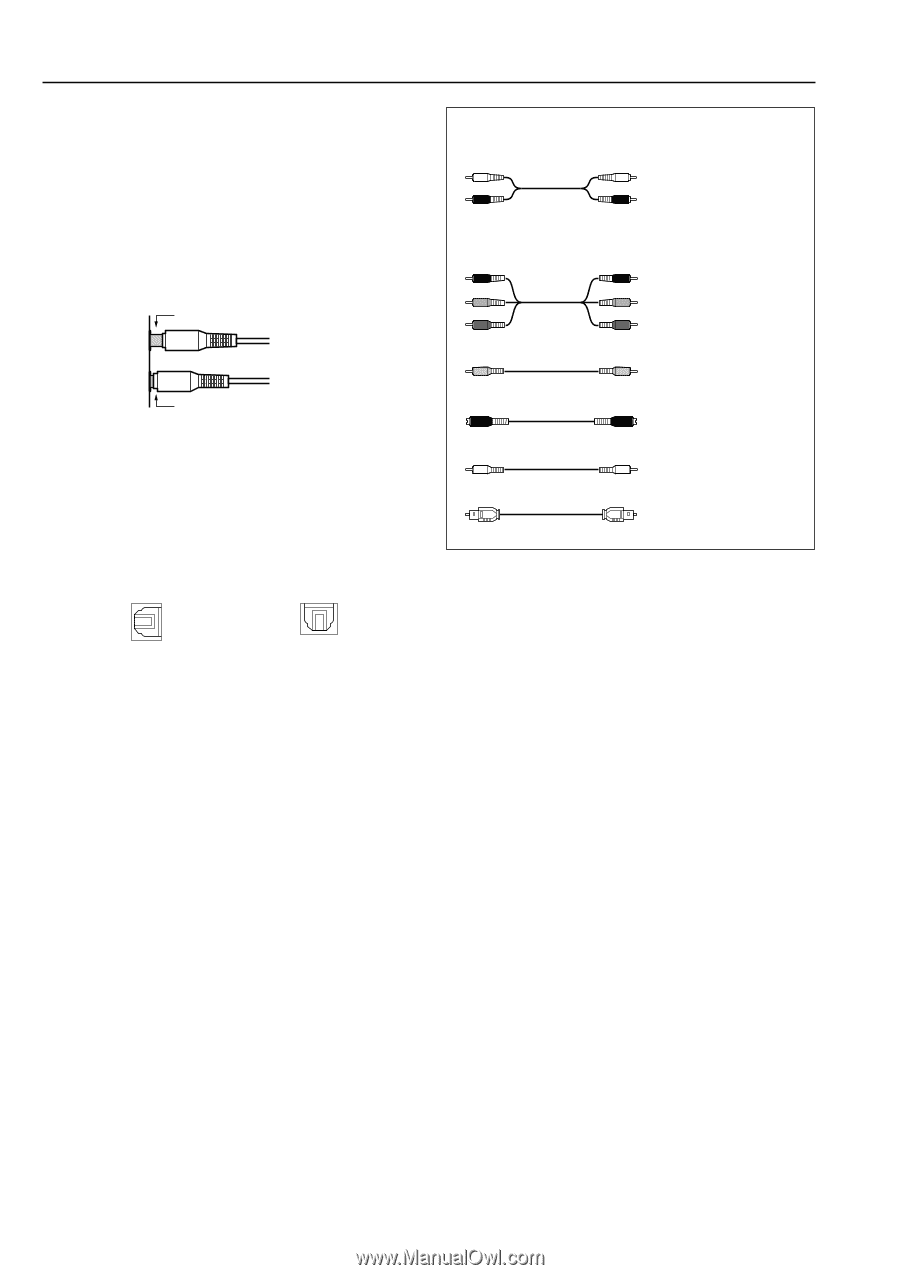
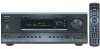
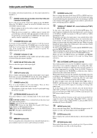
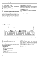
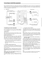
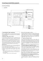
Connecting to Audio/Video equipment • Be sure to always refer to the instructions that came with the component that you are connecting. • Do not plug in the power cord until all connections have been properly made. • For input jacks, red connectors (marked R) are used for the right channel, white connectors (marked L) are used for the left channel, and yellow connectors (marked V) are used for video connection. • Insert all plugs and connectors securely. Improper connections can result in noise, poor performance, or damage to the equipment. Improper connection Cables are depicted in the connection diagrams as shown below. Left (white) L Audio connection cable Right (red) R PR PR PB PB Component video Y Y connection cable Inserted completely • Do not bind audio/video connection cables with power cords and speaker cables. Doing so may adversely affect the picture and sound quality. • The optical digital jacks are all of the shutter-type construction. Connect an optical cable by first making sure the cable is oriented correctly and then inserting it into the jack pushing the shutter lid inwards. Rear optical jack Front optical jack Video connection cable S video connection cable Coaxial cable Optical cable 14
-
 1
1 -
2
-
3
-
4
-
5
-
6
-
7
-
8
-
 9
9 -
 10
10 -
 11
11 -
 12
12 -
 13
13 -
 14
14 -
 15
15 -
 16
16 -
 17
17 -
 18
18 -
 19
19 -
20
-
21
-
22
-
23
-
24
-
25
-
26
-
27
-
28
-
29
-
30
-
31
-
32
-
33
-
34
-
35
-
36
-
37
-
38
-
39
-
40
-
41
-
42
-
43
-
44
-
45
-
46
-
47
-
48
-
49
-
50
-
51
-
52
-
53
-
54
-
55
-
56
-
57
-
58
-
59
-
60
-
61
-
62
-
63
-
64
-
65
-
66
-
67
-
68
-
69
-
70
-
71
-
72
-
73
-
74
-
75
-
76
 |
 |