Philips PXG30 User Manual - Page 9
Terminals
 |
UPC - 037849938089
View all Philips PXG30 manuals
Add to My Manuals
Save this manual to your list of manuals |
Page 9 highlights
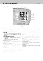
4. Functional Overview Terminals q w e rt Terminals y u i o !2 !1 !0 q Data 2 in Input socket for connecting computer output [ 5 BNC Type ( Red, Green, Blue, Horiz.sync., Vert.sync.)]. w Data 1 in Input socket for connecting computer output (Analog HDB 15-pin type) or 21-pin Scart (RGB) output from video equipment. e Data 3 in / Data out (Switchable) - Input socket for connecting computer output (Analog HDB 15-pin) - Output socket for connecting to a Data monitor. r Audio 1 in / Audio 2 in Input sockets for connecting audio output (stereo) from a computer. t Audio 3 in / out (Switchable) - Input socket for connecting audio output (stereo) from a computer. - Output socket for connecting an external audio amplifier. y Reset button A microprocessor included in the projector may occasionally malfunction and need to be reset. If necessary, press this button with a sharp tool to restart the unit. Do not use it excessively. u RS-232C port For connecting to mouse port of a computer which is controlled via the remote control of the projector. i S-video in Input socket for connecting S-video output from video equipment. o USB For connecting a PC or Apple Macintosh computer equipped with a USB downlink connection to control the mouse cursor of your computer via the remote control unit. !0 Video in Input socket for connecting the composite video output from video equipment. !1 Component video input Input socket for connecting the component video output from video equipment. !2 Audio in R / L Input sockets for connecting to Audio out sockets of video equipment. 9
-
 1
1 -
2
-
3
-
 4
4 -
 5
5 -
 6
6 -
 7
7 -
 8
8 -
 9
9 -
 10
10 -
 11
11 -
 12
12 -
 13
13 -
 14
14 -
15
-
16
-
17
-
18
-
19
-
20
-
21
-
22
-
23
-
24
-
25
-
26
-
27
-
28
-
29
-
30
-
31
-
32
-
33
-
34
-
35
-
36
-
37
-
38
-
39
-
40
-
41
-
42
-
43
-
44
-
45
-
46
-
47
-
48
-
49
-
50
-
51
-
52
 |
 |
